 |
ac5wzw00012276
DTC P02CA:00 [PCM (SKYACTIV-D 2.2)]
id0102j5212200
Engine Type
|
Item |
Reference |
|---|---|
|
Fuel injector (6 pin type), without SCR System
|
|
|
Fuel injector (6 pin type), with SCR System
|
Fuel Injector (6 pin type), Without SCR System
Details on DTCs
|
System malfunction location |
Large-type turbocharger area control system: Overboost |
|
|---|---|---|
|
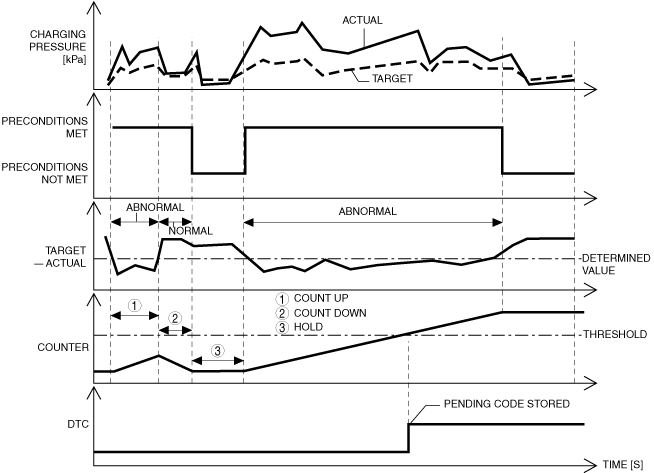
Detection condition
|
Determination condition
|
• As the result of comparing the actual boost pressure with the target boost pressure, the actual boost pressure exceeds the specification higher than the target boost pressure for a continuous 7 s.
|
|
Preconditions
|
• All of the following conditions are met when diesel particulate filter regeneration control is stopped during boost control feedback
|
|
|
Drive cycle
|
• 2
|
|
|
Self-test type
|
• CMDTC self test
|
|
|
Sensor/unit used
|
• MAP sensor
|
|
|
Fail-safe
|
• Not applicable
|
|
|
Vehicle status when DTCs are output
|
• Not applicable
|
|
|
Possible cause
|
• PCM input signal error
• Malfunction in vacuum piping and positive pressure piping of compressor bypass solenoid valve
• Regulating valve actuator malfunction
• Variable turbine geometry turbocharger actuator malfunction
• Compressor bypass solenoid valve malfunction
• Regulating valve actuator position sensor malfunction
• Variable turbine geometry turbocharger actuator position sensor malfunction
• PCM malfunction
|
|
System Wiring Diagram
Function Explanation (DTC Detection Outline)
ac5wzw00012276
|
Repeatability Verification Procedure
PID Item/Simulation Item Used in Diagnosis
PID
|
Item name |
Outline |
Unit |
Display/condition |
|---|---|---|---|
|
INTK_MAPA
|
Manifold absolute pressure (No.2)
|
kPa
|
• Displays the manifold absolute pressure (No.2).
|
|
MAP_DSD
|
Manifold absolute pressure (No.2) desired value
|
kPa
|
• Displays the manifold absolute pressure (No.2) desired value.
|
|
REGVP
|
Regulating valve actuator position
|
mm
|
• Displays the regulating valve actuator position.
|
|
REGVP_DSD
|
Target value for regulating valve actuator position sensor
|
mm
|
• Displays the target value for the regulating valve actuator position.
|
|
VGTURB_ACT
|
Variable turbine geometry turbocharger actuator position
|
%
|
• Displays the variable turbine geometry turbocharger actuator position.
|
Simulation item
|
Item name |
Outline |
Unit |
Display/condition |
|---|---|---|---|
|
VGTURB_DSD
|
Variable turbine geometry turbocharger actuator position
|
%
|
• Changes % and forcibly drives/stops the variable turbine geometry turbocharger actuator.
|
Function Inspection Using M-MDS
|
Step |
Inspection |
Results |
Action |
|---|---|---|---|
|
1
|
PURPOSE: VERIFY DTC CAUSING FREEZE FRAME DATA
• Is DTC P02CA:00 causing the freeze frame data?
|
Yes
|
Go to the next step.
|
|
No
|
Inspect the DTC causing the freeze frame data.
|
||
|
2
|
PURPOSE: RECORD VEHICLE STATUS AT TIME OF DTC DETECTION TO UTILIZE WITH REPEATABILITY VERIFICATION
• Record the freeze frame data/snap shot data.
|
―
|
Go to the next step.
|
|
3
|
PURPOSE: VERIFY OTHER RELATED DTCs
• Switch the ignition OFF, and then switch it ON (engine off).
• Display the DTCs using the M-MDS.
• Has any DTC other than P02CA:00 been stored?
|
Yes
|
Repair the malfunctioning location according to the applicable DTC troubleshooting.
|
|
No
|
Go to the next step.
|
||
|
4
|
PURPOSE: VERIFY MAP SENSOR INPUT SIGNAL
• Start the engine and warm it up.
• Display the following PIDs using the M-MDS.
• Are the monitoring values normal?
|
Yes
|
Go to the troubleshooting procedure to perform the procedure from Step 1.
|
|
No
|
Go to the next step.
|
||
|
5
|
PURPOSE: INSPECT WIRING HARNESSES AND CONNECTORS FOR RELATED-SENSOR
• Display the following PIDs using the M-MDS.
• When the PCM and MAP sensor connector are shaken, does the PID value include a PID item which has changed?
|
Yes
|
Inspect the related wiring harnesses and connectors.
• Repair or replace the malfunctioning location.
Go to the troubleshooting procedure to perform the procedure from Step 5.
|
|
No
|
Go to the troubleshooting procedure to perform the procedure from Step 1.
|
||
|
6
|
PURPOSE: DETERMINE IF MALFUNCTION IS CAUSED BY REGULATING VALVE ACTUATOR POSITION SENSOR MALFUNCTION
• Inspect the regulating valve actuator position sensor.
• Is the regulating valve actuator position sensor normal?
|
Yes
|
Go to the troubleshooting procedure to perform the procedure from Step 1.
|
|
No
|
Inspect the related wiring harnesses and connectors.
• Repair or replace the malfunctioning location.
Go to the troubleshooting procedure to perform the procedure from Step 5.
|
||
|
7
|
PURPOSE: DETERMINE IF MALFUNCTION IS CAUSED BY VARIABLE TURBINE GEOMETRY TURBOCHARGER ACTUATOR POSITION SENSOR MALFUNCTION
• Inspect the variable turbine geometry turbocharger actuator position sensor.
• Is the variable turbine geometry turbocharger actuator position sensor normal?
|
Yes
|
Go to the troubleshooting procedure to perform the procedure from Step 1.
|
|
No
|
Inspect the related wiring harnesses and connectors.
• Repair or replace the malfunctioning location.
Go to the troubleshooting procedure to perform the procedure from Step 5.
|
Troubleshooting Diagnostic Procedure
|
Step |
Inspection |
Results |
Action |
|---|---|---|---|
|
1
|
PURPOSE: INSPECT VACUUM PIPING AND POSITIVE PRESSURE PIPING OF COMPRESSOR BYPASS SOLENOID VALVE
• Inspect the vacuum piping and positive pressure piping of the compressor bypass solenoid valve.
• Is there hose leakage or damage in the vacuum piping and positive pressure piping?
|
Yes
|
Repair or replace the malfunctioning location, then go to Step 5.
|
|
No
|
Go to the next step.
|
||
|
2
|
PURPOSE: INSPECT COMPRESSOR BYPASS SOLENOID VALVE
• Inspect the compressor bypass solenoid valve.
• Is the compressor bypass solenoid valve normal?
|
Yes
|
Go to the next step.
|
|
No
|
Replace the compressor bypass solenoid valve, then go to Step 5.
|
||
|
3
|
PURPOSE: INSPECT REGULATING VALVE ACTUATOR
• Inspect the regulating valve actuator.
• Is the regulating valve actuator normal?
|
Yes
|
Go to the next step.
|
|
No
|
Replace the regulating valve actuator, then go to Step 5.
|
||
|
4
|
PURPOSE: INSPECT VARIABLE TURBINE GEOMETRY TURBOCHARGER ACTUATOR
• Inspect the variable turbine geometry turbocharger actuator.
• Is the variable turbine geometry turbocharger actuator normal?
|
Yes
|
Go to the next step.
|
|
No
|
Replace the variable turbine geometry turbocharger actuator, then go to Step 5.
|
||
|
5
|
PURPOSE: VERIFICATION OF VEHICLE REPAIR COMPLETION
• Reconnect all disconnected connectors and hoses.
• Refer to the [MEMORY CLEARING PROCEDURE] and clear the DTC.
• Implement the repeatability verification procedure.
• Display the DTCs using the M-MDS.
• Is DTC P02CA:00 displayed?
|
Yes
|
Repeat the inspection from Step 1.
• If the malfunction recurs, replace the PCM, then go to the next step.
|
|
No
|
Go to the next step.
|
||
|
6
|
PURPOSE: VERIFY IF THERE IS ANY OTHER MALFUNCTION
• Has any other DTC or pending code been stored?
|
Yes
|
Repair the malfunctioning location according to the applicable DTC troubleshooting.
|
|
No
|
DTC troubleshooting completed.
|
Fuel Injector (6 pin type), With SCR System
Details on DTCs
|
System malfunction location |
Large-type turbocharger area control system: Overboost |
|
|---|---|---|
|
Detection condition
|
Determination condition
|
• As the result of comparing the actual boost pressure with the target boost pressure, the actual boost pressure exceeds the specification higher than the target boost pressure for a continuous 7 s.
|
|
Preconditions
|
• All of the following conditions are met when diesel particulate filter regeneration control is stopped during boost control feedback
|
|
|
Drive cycle
|
• 2
|
|
|
Self-test type
|
• CMDTC self test
|
|
|
Sensor/unit used
|
• MAP sensor
|
|
|
Fail-safe
|
• Not applicable
|
|
|
Vehicle status when DTCs are output
|
• Not applicable
|
|
|
Possible cause
|
• PCM input signal error
• Malfunction in vacuum piping and positive pressure piping of compressor bypass solenoid valve
• Regulating valve actuator malfunction
• Variable turbine geometry turbocharger actuator malfunction
• Compressor bypass solenoid valve malfunction
• Regulating valve actuator position sensor malfunction
• Variable turbine geometry turbocharger actuator position sensor malfunction
• PCM malfunction
|
|
System Wiring Diagram
Function Explanation (DTC Detection Outline)
am6zzw00014396
|
Repeatability Verification Procedure
PID Item/Simulation Item Used in Diagnosis
PID
|
Item name |
Outline |
Unit |
Display/condition |
|---|---|---|---|
|
INTK_MAPA
|
Manifold absolute pressure (No.2)
|
kPa
|
• Displays the manifold absolute pressure (No.2).
|
|
MAP_DSD
|
Manifold absolute pressure (No.2) desired value
|
kPa
|
• Displays the manifold absolute pressure (No.2) desired value.
|
|
REGVP
|
Regulating valve actuator position
|
mm
|
• Displays the regulating valve actuator position.
|
|
REGVP_DSD
|
Target value for regulating valve actuator position sensor
|
mm
|
• Displays the target value for the regulating valve actuator position.
|
|
VGTURB_ACT
|
Variable turbine geometry turbocharger actuator position
|
%
|
• Displays the variable turbine geometry turbocharger actuator position.
|
Simulation item
|
Item name |
Outline |
Unit |
Display/condition |
|---|---|---|---|
|
VGTURB_DSD
|
Variable turbine geometry turbocharger actuator position
|
%
|
• Changes % and forcibly drives/stops the variable turbine geometry turbocharger actuator.
|
Function Inspection Using M-MDS
|
Step |
Inspection |
Results |
Action |
|---|---|---|---|
|
1
|
PURPOSE: VERIFY DTC CAUSING FREEZE FRAME DATA
• Is DTC P02CA:00 causing the freeze frame data?
|
Yes
|
Go to the next step.
|
|
No
|
Inspect the DTC causing the freeze frame data.
|
||
|
2
|
PURPOSE: RECORD VEHICLE STATUS AT TIME OF DTC DETECTION TO UTILIZE WITH REPEATABILITY VERIFICATION
• Record the freeze frame data/snap shot data.
|
―
|
Go to the next step.
|
|
3
|
PURPOSE: VERIFY OTHER RELATED DTCs
• Switch the ignition OFF, and then switch it ON (engine off).
• Display the DTCs using the M-MDS.
• Has any DTC other than P02CA:00 been stored?
|
Yes
|
Repair the malfunctioning location according to the applicable DTC troubleshooting.
|
|
No
|
Go to the next step.
|
||
|
4
|
PURPOSE: VERIFY MAP SENSOR INPUT SIGNAL
• Start the engine and warm it up.
• Display the following PIDs using the M-MDS.
• Are the monitoring values normal?
|
Yes
|
Go to Troubleshooting Diagnostic Procedure to perform the procedure from step 1.
|
|
No
|
Go to the next step.
|
||
|
5
|
PURPOSE: INSPECT WIRING HARNESSES AND CONNECTORS FOR RELATED-SENSOR
• Display the following PIDs using the M-MDS.
• When the PCM and MAP sensor connector are shaken, does the PID value include a PID item which has changed?
|
Yes
|
Inspect the related wiring harnesses and connectors.
• Repair or replace the malfunctioning location.
Go to Troubleshooting Diagnostic Procedure to perform the procedure from step 5.
|
|
No
|
Go to Troubleshooting Diagnostic Procedure to perform the procedure from step 1.
|
||
|
6
|
PURPOSE: DETERMINE IF MALFUNCTION IS CAUSED BY REGULATING VALVE ACTUATOR POSITION SENSOR MALFUNCTION
• Inspect the regulating valve actuator position sensor.
• Is the regulating valve actuator position sensor normal?
|
Yes
|
Go to Troubleshooting Diagnostic Procedure to perform the procedure from step 1.
|
|
No
|
Inspect the related wiring harnesses and connectors.
• Repair or replace the malfunctioning location.
Go to Troubleshooting Diagnostic Procedure to perform the procedure from step 5.
|
||
|
7
|
PURPOSE: DETERMINE IF MALFUNCTION IS CAUSED BY VARIABLE TURBINE GEOMETRY TURBOCHARGER ACTUATOR POSITION SENSOR MALFUNCTION
• Inspect the variable turbine geometry turbocharger actuator position sensor.
• Is the variable turbine geometry turbocharger actuator position sensor normal?
|
Yes
|
Go to Troubleshooting Diagnostic Procedure to perform the procedure from step 1.
|
|
No
|
Inspect the related wiring harnesses and connectors.
• Repair or replace the malfunctioning location.
Go to Troubleshooting Diagnostic Procedure to perform the procedure from step 5.
|
Troubleshooting Diagnostic Procedure
|
Step |
Inspection |
Results |
Action |
|---|---|---|---|
|
1
|
PURPOSE: INSPECT VACUUM PIPING AND POSITIVE PRESSURE PIPING OF COMPRESSOR BYPASS SOLENOID VALVE
• Inspect the vacuum piping and positive pressure piping of the compressor bypass solenoid valve.
• Is there hose leakage or damage in the vacuum piping and positive pressure piping?
|
Yes
|
Repair or replace the malfunctioning location, then go to Step 5.
|
|
No
|
Go to the next step.
|
||
|
2
|
PURPOSE: INSPECT COMPRESSOR BYPASS SOLENOID VALVE
• Inspect the compressor bypass solenoid valve.
• Is the compressor bypass solenoid valve normal?
|
Yes
|
Go to the next step.
|
|
No
|
Replace the compressor bypass solenoid valve, then go to Step 5.
|
||
|
3
|
PURPOSE: INSPECT REGULATING VALVE ACTUATOR
• Inspect the regulating valve actuator.
• Is the regulating valve actuator normal?
|
Yes
|
Go to the next step.
|
|
No
|
Replace the regulating valve actuator, then go to Step 5.
|
||
|
4
|
PURPOSE: INSPECT VARIABLE TURBINE GEOMETRY TURBOCHARGER ACTUATOR
• Inspect the variable turbine geometry turbocharger actuator.
• Is the variable turbine geometry turbocharger actuator normal?
|
Yes
|
Go to the next step.
|
|
No
|
Replace the variable turbine geometry turbocharger actuator, then go to Step 5.
|
||
|
5
|
PURPOSE: VERIFICATION OF VEHICLE REPAIR COMPLETION
• Reconnect all disconnected connectors and hoses.
• Refer to the [MEMORY CLEARING PROCEDURE] and clear the DTC.
• Implement the repeatability verification procedure.
• Display the DTCs using the M-MDS.
• Is DTC P02CA:00 displayed?
|
Yes
|
Repeat the inspection from Step 1.
• If the malfunction recurs, replace the PCM, then go to the next step.
|
|
No
|
Go to the next step.
|
||
|
6
|
PURPOSE: VERIFY IF THERE IS ANY OTHER MALFUNCTION
• Has any other DTC or pending code been stored?
|
Yes
|
Repair the malfunctioning location according to the applicable DTC troubleshooting.
|
|
No
|
DTC troubleshooting completed.
|
