 |
am6zzw00017824
DTC P004A:00 [PCM (SKYACTIV-D 2.2)]
id0102j5217000
Details on DTCs
|
System malfunction location |
Variable turbine geometry turbocharger actuator control circuit problem |
|
|---|---|---|
|
Detection condition
|
Determination conditions
|
• The variable turbine geometry turbocharger actuator control duty value is 90% or more for a continuous 3 s.
|
|
Preconditions
|
• All of the following conditions are met.
|
|
|
Drive cycle
|
• 1
|
|
|
Self-test type
|
• CMDTC self test
|
|
|
Sensor/unit used
|
• Variable turbine geometry turbocharger actuator
• Variable turbine geometry turbocharger actuator position sensor
|
|
|
Fail-safe
|
• Limits engine torque.
• Inhibits the automatic diesel particulate filter regeneration control.
• Inhibits the manual diesel particulate filter regeneration control.
• Inhibits the boost control.
• Inhibits the EGR control.
• Stops the G-vectoring control (GVC).
• Limits the engine transaxle total control.
|
|
|
Vehicle status when DTCs are output
|
• Check engine light turns on
|
|
|
Possible Cause
|
• Variable turbine geometry turbocharger actuator/variable turbine geometry turbocharger actuator position sensor connector or terminal malfunction
• PCM connector or terminal malfunction
• Short to power supply in wiring harness between the following terminals
• Short to ground in wiring harness between the following terminals:
• Open circuit in wiring harness between the following terminals:
• Variable turbine geometry turbocharger actuator position sensor malfunction
• Variable turbine geometry turbocharger actuator malfunction
• PCM malfunction
|
|
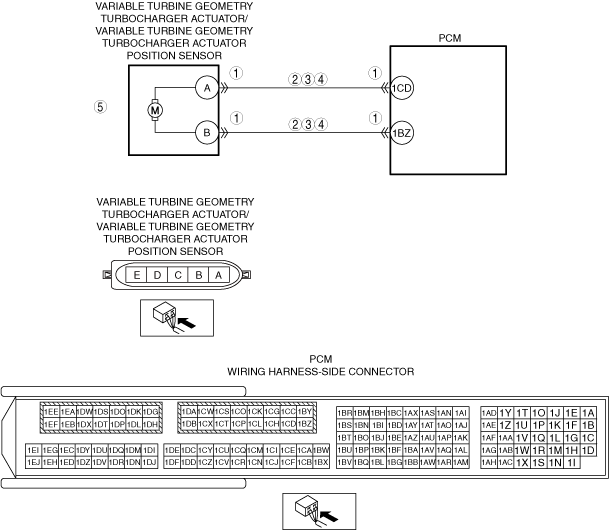
System Wiring Diagram
am6zzw00017824
|
Function Explanation (DTC Detection Outline)
Repeatability Verification Procedure
PID Item/Simulation Item Used in Diagnosis
PID
|
Item name |
Outline |
Unit |
Display/condition |
|---|---|---|---|
|
VGTURB_ACT
|
Variable turbine geometry turbocharger actuator position
|
%
|
• Displays the variable turbine geometry turbocharger actuator position.
|
Simulation item
|
Item name |
Outline |
Unit |
Display/condition |
|---|---|---|---|
|
VGTURB_DSD
|
Variable turbine geometry turbocharger actuator position
|
%
|
• Changes % and forcibly drives/stops the variable turbine geometry turbocharger actuator.
|
Function Inspection Using M-MDS
|
Step |
Inspection |
Results |
Action |
|---|---|---|---|
|
1
|
PURPOSE: RECORD VEHICLE STATUS AT TIME OF DTC DETECTION TO UTILIZE WITH REPEATABILITY VERIFICATION
• Record the freeze frame data/snap shot data.
|
—
|
Go to the next step.
|
|
2
|
PURPOSE: DETERMINE IF MALFUNCTION IS CAUSED BY VARIABLE TURBINE GEOMETRY TURBOCHARGER ACTUATOR POSITION SENSOR MALFUNCTION
• Inspect the variable turbine geometry turbocharger actuator position sensor.
• Is the variable turbine geometry turbocharger actuator position sensor normal?
|
Yes
|
Go to Troubleshooting Diagnostic Procedure to perform the procedure from step 1.
|
|
No
|
Inspect the related wiring harnesses and connectors.
• Repair or replace the malfunctioning location.
Go to Troubleshooting Diagnostic Procedure to perform the procedure from step 5.
|
Troubleshooting Diagnostic Procedure
|
Step |
Inspection |
Results |
Action |
|---|---|---|---|
|
1
|
PURPOSE: VERIFY IF CONNECTOR DAMAGE OF EACH PART AFFECTS DIAGNOSTIC RESULTS
• Switch the ignition OFF.
• Disconnect the connectors of the following parts:
• Inspect the connector engagement and connection condition, and inspect the terminals for damage, deformation, corrosion, or disconnection.
• Is the connector normal?
|
Yes
|
Go to the next step.
|
|
No
|
Repair or replace the connector, then go to Step 6.
|
||
|
2
|
PURPOSE: VERIFY IF SHORT TO POWER SUPPLY IN VARIABLE TURBINE GEOMETRY TURBOCHARGER ACTUATOR CIRCUIT AFFECTS DIAGNOSTIC RESULTS
• Verify that the variable turbine geometry turbocharger actuator/variable turbine geometry turbocharger actuator position sensor connector and the PCM connector are disconnected.
• Switch the ignition ON (engine off).
• Measure the voltage at the following terminals (vehicle wiring harness side).
• Is the voltage 0 V?
|
Yes
|
Go to the next step.
|
|
No
|
Refer to the wiring diagram and verify if there is a common connector between the following terminals.
• Variable turbine geometry turbocharger actuator/variable turbine geometry turbocharger actuator position sensor terminal B and PCM terminal 1BZ
• Variable turbine geometry turbocharger actuator/variable turbine geometry turbocharger actuator position sensor terminal A and PCM terminal 1CD
If there is a common connector:
If there is no common connector:
Go to Step 6.
|
||
|
3
|
PURPOSE: VERIFY IF SHORT TO GROUND IN VARIABLE TURBINE GEOMETRY TURBOCHARGER ACTUATOR CIRCUIT AFFECTS DIAGNOSTIC RESULTS
• Verify that the variable turbine geometry turbocharger actuator/variable turbine geometry turbocharger actuator position sensor connector and the PCM connector are disconnected.
• Switch the ignition OFF.
• Inspect for continuity between the following terminals (vehicle wiring harness side) and ground.
• Is there continuity?
|
Yes
|
• Refer to the wiring diagram and verify if there is a common connector between the following terminals.
|
|
No
|
Go to the next step.
|
||
|
4
|
PURPOSE: VERIFY IF OPEN CIRCUIT IN VARIABLE TURBINE GEOMETRY TURBOCHARGER ACTUATOR CIRCUIT AFFECTS DIAGNOSTIC RESULTS
• Verify that the variable turbine geometry turbocharger actuator/variable turbine geometry turbocharger actuator position sensor connector and the PCM connector are disconnected.
• Inspect between the following terminals (vehicle wiring harness side) for continuity.
• Is there continuity?
|
Yes
|
Go to Step 6.
|
|
No
|
Refer to the wiring diagram and verify if there is a common connector between the following terminals.
• Variable turbine geometry turbocharger actuator/variable turbine geometry turbocharger actuator position sensor terminal B and PCM terminal 1BZ
• Variable turbine geometry turbocharger actuator/variable turbine geometry turbocharger actuator position sensor terminal A and PCM terminal 1CD
If there is a common connector:
If there is no common connector:
Go to Step 6.
|
||
|
5
|
PURPOSE: INSPECT VARIABLE TURBINE GEOMETRY TURBOCHARGER ACTUATOR
• Inspect the variable turbine geometry turbocharger actuator.
• Is the variable turbine geometry turbocharger actuator normal?
|
Yes
|
Go to the next step.
|
|
No
|
Replace the variable turbine geometry turbocharger actuator, then go to the next step.
|
||
|
6
|
PURPOSE: VERIFICATION OF VEHICLE REPAIR COMPLETION
• Reconnect all disconnected connectors and hoses.
• Refer to the [MEMORY CLEARING PROCEDURE] and clear the DTC.
• Implement the repeatability verification procedure.
• Display the DTCs using the M-MDS.
• Is DTC P004A:00 displayed?
|
Yes
|
Repeat the inspection from Step 1.
• If the malfunction recurs, replace the PCM, then go to the next step.
|
|
No
|
Go to the next step.
|
||
|
7
|
PURPOSE: VERIFY IF THERE IS ANY OTHER MALFUNCTION
• Has any other DTC or pending code been stored?
|
Yes
|
Repair the malfunctioning location according to the applicable DTC troubleshooting.
|
|
No
|
DTC troubleshooting completed.
|