|
1
|
RECORD VEHICLE STATUS AT TIME OF DTC DETECTION TO UTILIZE WITH REPEATABILITY VERIFICATION
-
Note
-
• Recording can be facilitated using the screen capture function of the PC.
• Record the snapshot data on the repair order.
|
—
|
Go to the next step.
|
|
2
|
VERIFY DTCs RELATED TO UREA PUMP
• Perform the DTC Reading Procedure.
• Has a DTC related to the UREA pump been stored?
|
Yes
|
Go to the applicable DTC inspection.
|
|
No
|
Go to the next step.
|
|
3
|
INSPECT UREA TANK
• Visually inspect the urea tank.
• Are there any damage or deformation at the urea tank?
|
Yes
|
Replace the urea tank, then go to the Step 10.
|
|
No
|
Go to the next step.
|
|
4
|
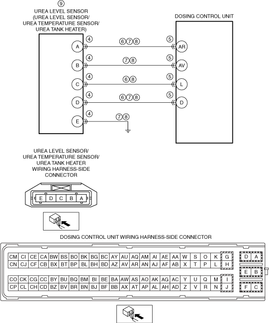
INSPECT UREA LEVEL SENSOR/UREA TEMPERATURE SENSOR/UREA TANK HEATER CONNECTOR CONDITION
• Switch the ignition off.
• Disconnect the urea level sensor/urea temperature sensor/urea tank heater connector.
• Inspect for poor connection (such as damaged/pulled-out pins, corrosion).
• Is there any malfunction?
|
Yes
|
Repair or replace the connector and/or terminals, then go to Step 10.
|
|
No
|
Go to the next step.
|
|
5
|
INSPECT DOSING CONTROL UNIT CONNECTOR CONDITION
• Disconnect the dosing control unit connector.
• Inspect for poor connection (such as damaged/pulled-out pins, corrosion).
• Is there any malfunction?
|
Yes
|
Repair or replace the connector and/or terminals, then go to Step 10.
|
|
No
|
Go to the next step.
|
|
6
|
INSPECT UREA LEVEL SENSOR CIRCUIT FOR SHORT TO GROUND
• Verify that the urea level sensor/urea temperature sensor/urea tank heater and dosing control unit connectors are disconnected.
• Inspect for continuity between the following terminals (wiring harness-side) and body ground:
-
― Urea level sensor/urea temperature sensor/urea tank heater terminal A
― Urea level sensor/urea temperature sensor/urea tank heater terminal C
― Urea level sensor/urea temperature sensor/urea tank heater terminal D
• Is there continuity?
|
Yes
|
Refer to the wiring diagram and verify whether or not there is a common connector between the following terminals:
• Urea level sensor/urea temperature sensor/urea tank heater terminal A—dosing control unit terminal AR
• Urea level sensor/urea temperature sensor/urea tank heater terminal C—dosing control unit terminal L
• Urea level sensor/urea temperature sensor/urea tank heater terminal D—dosing control unit terminal D
If there is a common connector:
• Determine the malfunctioning part by inspecting the common connector and the terminal for corrosion, damage, or pin disconnection, and the common wiring harness for a short to ground.
• Repair or replace the malfunctioning part.
If there is no common connector:
• Repair or replace the wiring harness which has a short to ground.
Go to Step 10.
|
|
No
|
Go to the next step.
|
|
7
|
INSPECT UREA LEVEL SENSOR SIGNAL CIRCUIT FOR SHORT TO POWER SUPPLY
• Verify that the urea level sensor/urea temperature sensor/urea tank heater and dosing control unit connectors are disconnected.
• Switch the ignition ON (engine off).
-
Note
-
• Another DTC may be stored by the dosing control unit detecting an open circuit.
• Measure the voltage at the following terminals (wiring harness-side).
-
― Urea level sensor/urea temperature sensor/urea tank heater terminal A
― Urea level sensor/urea temperature sensor/urea tank heater terminal B
― Urea level sensor/urea temperature sensor/urea tank heater terminal D
― Urea level sensor/urea temperature sensor/urea tank heater terminal E
• Is the voltage 0 V?
|
Yes
|
Go to the next step.
|
|
No
|
Refer to the wiring diagram and verify whether or not there is a common connector between the following terminals:
• Urea level sensor/urea temperature sensor/urea tank heater terminal A—dosing control unit terminal AR
• Urea level sensor/urea temperature sensor/urea tank heater terminal B—dosing control unit terminal AV
• Urea level sensor/urea temperature sensor/urea tank heater terminal D—dosing control unit terminal D
• Urea level sensor/urea temperature sensor/urea tank heater terminal E—body GND
If there is a common connector:
• Determine the malfunctioning part by inspecting the common connector and the terminal for corrosion, damage, or pin disconnection, and the common wiring harness for a short to power supply.
• Repair or replace the malfunctioning part.
If there is no common connector:
• Repair or replace the wiring harness which has a short to power supply.
Go to Step 10.
|
|
8
|
INSPECT UREA LEVEL SENSOR CIRCUIT FOR OPEN CIRCUIT
• Verify that the urea level sensor/urea temperature sensor/urea tank heater and dosing control unit connectors are disconnected.
• Switch the ignition off.
• Inspect for continuity between the following terminals (wiring harness-side):
-
― Urea level sensor/urea temperature sensor/urea tank heater terminal A—dosing control unit terminal AR
― Urea level sensor/urea temperature sensor/urea tank heater terminal B—dosing control unit terminal AV
― Urea level sensor/urea temperature sensor/urea tank heater terminal C—dosing control unit terminal L
― Urea level sensor/urea temperature sensor/urea tank heater terminal D—dosing control unit terminal D
― Urea level sensor/urea temperature sensor/urea tank heater terminal E—body GND
• Is there continuity?
|
Yes
|
Go to the next step.
|
|
No
|
Refer to the wiring diagram and verify whether or not there is a common connector between the following terminals:
• Urea level sensor/urea temperature sensor/urea tank heater terminal A—dosing control unit terminal AR
• Urea level sensor/urea temperature sensor/urea tank heater terminal B—dosing control unit terminal AV
• Urea level sensor/urea temperature sensor/urea tank heater terminal C—dosing control unit terminal L
• Urea level sensor/urea temperature sensor/urea tank heater terminal D—dosing control unit terminal D
• Urea level sensor/urea temperature sensor/urea tank heater terminal E—body GND
If there is a common connector:
• Determine the malfunctioning part by inspecting the common connector and the terminal for corrosion, damage, or pin disconnection, and the common wiring harness for an open circuit.
• Repair or replace the malfunctioning part.
If there is no common connector:
• Repair or replace the wiring harness which has an open circuit.
Go to Step 10.
|
|
9
|
INSPECT UREA LEVEL SENSOR
• Inspect the urea level sensor.
• Is there any malfunction?
|
Yes
|
Replace the urea level sensor/urea temperature sensor/urea tank heater, then go to the next step.
|
|
No
|
Go to the next step.
|
|
10
|
VERIFY IF MALFUNCTION CAUSE IS AdBlue® OVERFILLING
• Verify the AdBlue ® amount.
• Is the AdBlue® amount appropriate?
|
Yes
|
Go to the applicable DTC inspection.
|
|
No
|
Go to the next step.
|
|
11
|
VERIFY DTC TROUBLESHOOTING COMPLETED
• Always reconnect all disconnected connectors.
• Clear the DTC from the dosing control unit memory using the M-MDS.
-
Warning
-
• While performing this step, always operate the vehicle in a safe and lawful manner.
• When the M-MDS is used to observe monitor system status while driving, be sure to have another technician with you, or record the data in the M-MDS using the PID/DATA MONITOR AND RECORD capturing function and inspect later.
• Perform the followings:
-
1. Perform the "COMPULSORY DIESEL PARTICULATE FILTER REGENERATION".
2. After accelerating to 100 km/h {62.1 mph}, stop the vehicle at the deceleration speed exceeding 9 km/h {6 mph} for 1 s.
3. Stop the vehicle for 20 s.
4. Repeat Steps 2 and 3 four times or more.
• Retrieve the dosing control unit DTCs using the M-MDS.
• Is the same Pending DTC present?
|
Yes
|
Repeat the inspection from Step 1.
• If the malfunction recurs, replace the dosing control unit.
Go to the next step.
|
|
No
|
Go to the next step.
|
|
12
|
VERIFY IF OTHER DTCs DISPLAYED
• Are any other DTCs displayed?
|
Yes
|
Repair or replace the malfunctioning part according to the applicable DTC troubleshooting.
|
|
No
|
DTC troubleshooting completed.
|