DTC U3003:16/U3003:17/U3003:1C [DYNAMIC STABILITY CONTROL (DSC)]
id0402b2880500
DTC |
U3003:16, U3003:17, U3003:1C |
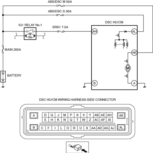
Power supply system |
|
---|---|---|---|
DETECTION CONDITION
|
• U3003:16
• U3003:17
• U3003:1C
|
||
FAIL-SAFE FUNCTION
|
• Refer to “Fail-safe Function Malfunction Contents”. (See DTC TABLE [DYNAMIC STABILITY CONTROL (DSC)].)
|
||
POSSIBLE CAUSE
|
• Poor connection at connectors (female terminal)
• Battery deterioration
• Generator malfunction
• Malfunction of fuse (MAIN 200A, ABS/DSC M 50A, ABS/DSC S 30A or SRS1 7.5 A)
• Open or short circuit in wiring harness between DSC HU/CM terminal AH and battery positive terminal
• Open or short circuit in wiring harness between DSC HU/CM terminal AK and battery positive terminal
• Open or short circuit in wiring harness between DSC HU/CM terminal AL and battery positive terminal
• Open circuit in wiring harness between DSC HU/CM terminal B and body ground
• DSC HU/CM malfunction
|
||
![]() |
Diagnostic Procedure
STEP |
INSPECTION |
ACTION |
|
---|---|---|---|
1
|
INSPECT BATTERY VOLTAGE
• Is the battery positive terminal voltage normal?
|
Yes
|
Inspect for normal connection of the battery terminals.
Go to the next step.
|
No
|
Charge or replace the battery, then go to Step 7.
(See BATTERY RECHARGING.)
|
||
2
|
INSPECT BATTERY GRAVITY
• Is battery specific gravity as specified?
(See BATTERY INSPECTION.)
|
Yes
|
Go to the next step.
|
No
|
Replace the battery, then go to Step 7.
|
||
3
|
INSPECT CHARGING SYSTEM
• Are the generator and the drive belt tensions normal?
|
Yes
|
Go to the next step.
|
No
|
Replace the generator and/or drive belt if necessary.
(See DRIVE BELT REMOVAL/INSTALLATION [SKYACTIV-G 2.0, SKYACTIV-G 2.5 (WITHOUT CYLINDER DEACTIVATION)].)
Go to Step 7.
|
||
4
|
INSPECT DSC FUSE CONDITION
• Is the DSC fuse (MAIN 200A, ABS/DSC M 50A, ABS/DSC S 30A and SRS1 7.5A) normal?
|
Yes
|
Go to the next step.
|
No
|
Replace the fuse, then go to Step 7.
|
||
5
|
INSPECT DSC HU/CM POWER SUPPLY FOR OPEN CIRCUIT
• Disconnect the DSC HU/CM connector.
• Switch the ignition ON.
• Measure the voltage between following connector terminals of the DSC HU/CM (wiring harness-side) and body ground:
• Is the voltage 10 V or more?
|
Yes
|
Go to the next step.
|
No
|
Repair or replace the wiring harness, then go to Step 7.
|
||
6
|
INSPECT DSC HU/CM GROUND FOR POOR GROUND OR OPEN CIRCUIT
• Switch the ignition off.
• Measure the resistance between following connector terminal of DSC HU/CM (wiring harness-side) and body ground:
• Is the resistance within 0—1 ohm?
|
Yes
|
Go to the next step.
|
No
|
If there is open circuit:
• Repair or replace the wiring harness, then go to the next step.
If resistance is not within specification:
• Repair or replace the poor ground part, then go to the next step.
|
||
7
|
VERIFY DTC TROUBLESHOOTING COMPLETED
• Using the M-MDS, clear the DTC from the DSC HU/CM.
• Start the engine and drive the vehicle at 20 km/h {12 mph} or more.
• Gradually slow down and stop vehicle.
• Using the M-MDS, perform the DSC HU/CM DTC inspection.
• Is the same Pending DTC present?
|
Yes
|
Repeat the inspection from Step 1.
• If the malfunction recurs, replace the DSC HU/CM.
Go to the next step.
|
No
|
Go to the next step.
|
||
8
|
VERIFY NO DTC IS PRESENT
• Are any DTCs present?
|
Yes
|
Go to the applicable DTC inspection.
|
No
|
DTC troubleshooting completed.
|