 |
am6xuw00010530
STEERING GEAR AND LINKAGE DISASSEMBLY
id061300801800
1. Remove the wheels and tires. (See WHEEL AND TIRE REMOVAL/INSTALLATION.)
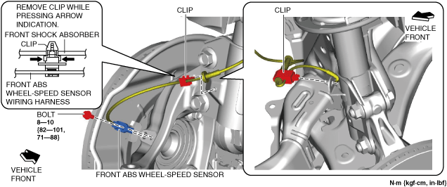
2. Disconnect the front ABS wheel-speed sensor wiring harness installed to the steering knuckle and set it aside.
am6xuw00010530
|
3. Remove the following parts:
4. Detach the tie-rod end from the steering knuckle. (See TIE-ROD END REPLACEMENT.)
5. Disconnect the front lower arm ball joint from the steering knuckle. (See FRONT LOWER ARM REMOVAL/INSTALLATION.)
6. Remove the joint cover. (See STEERING WHEEL AND COLUMN REMOVAL/INSTALLATION.)
7. Disconnect the intermediate shaft from the steering gear and linkage. (See STEERING WHEEL AND COLUMN REMOVAL/INSTALLATION.)
8. Remove the front crossmember component. (See FRONT CROSSMEMBER REMOVAL/INSTALLATION.)
9. Remove the steering gear and linkage from the front crossmember component. (See STEERING GEAR AND LINKAGE REMOVAL/INSTALLATION.)
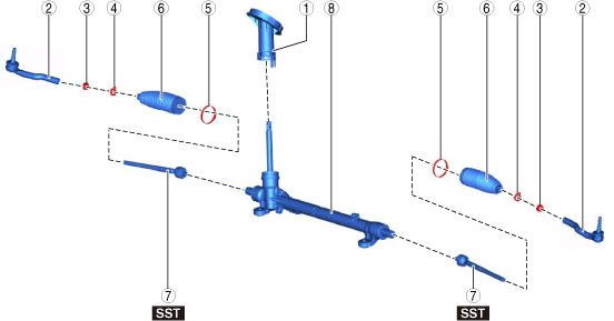
10. Disassemble in the order indicated in the figure.
L.H.D.
am6xuw00009747
|
R.H.D.
am6zzw00017052
|
|
1
|
Dust cover
|
|
2
|
Tie-rod end
(See Tie-rod End Disassembly Note.)
|
|
3
|
Locknut
|
|
4
|
Boot clamp
|
|
5
|
Boot band
(See Boot Band Disassembly Note.)
|
|
6
|
Boot
|
|
7
|
Tie rod
(See Tie Rod Disassembly Note.)
|
|
8
|
Steering gear
|
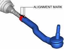
Tie-rod End Disassembly Note
1. Place alignment marks as shown in the figure for proper installation.
am6xuw00009748
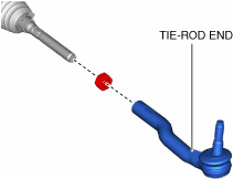
|
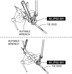
2. Remove the tie-rod end.
am6xuw00009749
|
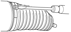
Boot Band Disassembly Note
1. Insert a flathead screwdriver into the crimped part of the boot band, expand the crimped part and remove the boot band.
ac5wzw00001035
|
Tie Rod Disassembly Note
1. Lock the steering rack end (pinion gear side) against rotation using a wrench and remove the tie rod using the SST.
am6xuw00009750
|