|
1
|
DETERMINE MALFUNCTIONING SPEAKER
• Perform diagnostic assist code “94” speaker inspection.
• Is audio produced from each speaker in order?
|
Yes
|
Go to Step 27.
|
|
No
|
No audio produced from front door speaker (LH) and tweeter (LH) (With tweeter)
• Go to the next step.
No audio produced from front door speaker (LH) (Without tweeter)
• Go to the next step.
No audio produced from front door speaker (RH) and tweeter (RH) (With tweeter)
• Go to Step 9.
No audio produced from front door speaker (RH) (Without tweeter)
• Go to Step 9.
No sound produced from rear door speaker (LH)
• Go to Step 16.
No audio produced from rear door speaker (RH)
• Go to Step 21.
No audio produced from all speakers.
• Go to Step 26.
|
|
2
|
INSPECT TUNER AND AMP UNIT (TAU) CONNECTOR CONDITION
• Switch the ignition off.
• Disconnect the negative battery terminal.
• Disconnect the tuner and amp unit (TAU) connector.
• Inspect the connector engagement and connection condition and inspect the terminals for damage, deformation, corrosion, or disconnection.
• Is the connector normal?
|
Yes
|
Go to the next step.
|
|
No
|
Repair or replace the connector, then go to Step 27.
|
|
3
|
INSPECT FRONT DOOR SPEAKER (LH) CONNECTOR CONDITION
• Disconnect the front door speaker (LH) connector.
• Inspect the connector engagement and connection condition and inspect the terminals for damage, deformation, corrosion, or disconnection.
• Is the connector normal?
|
Yes
|
With tweeter:
• Go to the next step.
Without tweeter:
• Go to Step 5.
|
|
No
|
Repair or replace the connector, then go to Step 27.
|
|
4
|
INSPECT TWEETER (LH) CONNECTOR CONDITION
• Disconnect the tweeter (LH) connector.
• Inspect the connector engagement and connection condition and inspect the terminals for damage, deformation, corrosion, or disconnection.
• Is the connector normal?
|
Yes
|
Go to the next step.
|
|
No
|
Repair or replace the connector, then go to Step 27.
|
|
5
|
INSPECT FRONT DOOR SPEAKER (LH) CIRCUIT FOR SHORT TO GROUND
• Verify that the following connectors are disconnected.
-
― Tuner and amp unit (TAU)
― Front door speaker (LH)
― Tweeter (LH) (With tweeter)
• Inspect for continuity between the following terminals (wiring harness-side) and body ground.
-
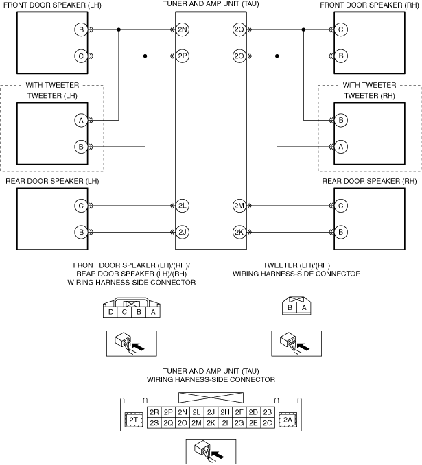
― Front door speaker (LH) terminal B
― Front door speaker (LH) terminal C
• Is there continuity?
|
Yes
|
Refer to the wiring diagram and verify if there is a common connector between the following terminals.
• Tuner and amp unit (TAU) terminal 2N and front door speaker (LH) terminal B
• Tuner and amp unit (TAU) terminal 2P and front door speaker (LH) terminal C
• Tuner and amp unit (TAU) terminal 2N and tweeter (LH) terminal A (With tweeter)
• Tuner and amp unit (TAU) terminal 2P and tweeter (LH) terminal B (With tweeter)
If there is a common connector:
• Inspect the common connector and terminals for corrosion, damage, or disconnection and the common wiring harnesses for short to ground to determine the malfunctioning location.
• Repair or replace the malfunctioning location.
If there is no common connector:
• Repair or replace the wiring harness which is shorted to ground.
Go to Step 27.
|
|
No
|
Go to the next step.
|
|
6
|
INSPECT FRONT DOOR SPEAKER (LH) CIRCUIT FOR SHORT TO POWER SUPPLY
• Verify that the following connectors are disconnected.
-
― Tuner and amp unit (TAU)
― Front door speaker (LH)
― Tweeter (LH) (With tweeter)
• Reconnect the negative battery terminal.
• Switch the ignition ON (engine off or on).
• Measure the voltage at the following terminals (wiring harness-side).
-
― Front door speaker (LH) terminal B
― Front door speaker (LH) terminal C
• Is the voltage 0 V?
|
Yes
|
Go to the next step.
|
|
No
|
Refer to the wiring diagram and verify if there is a common connector between the following terminals.
• Tuner and amp unit (TAU) terminal 2N and front door speaker (LH) terminal B
• Tuner and amp unit (TAU) terminal 2P and front door speaker (LH) terminal C
• Tuner and amp unit (TAU) terminal 2N and tweeter (LH) terminal A (With tweeter)
• Tuner and amp unit (TAU) terminal 2P and tweeter (LH) terminal B (With tweeter)
If there is a common connector:
• Inspect the common connector and terminals for corrosion, damage, or disconnection and the common wiring harnesses for short to power supply to determine the malfunctioning location.
• Repair or replace the malfunctioning location.
If there is no common connector:
• Repair or replace the wiring harness which is shorted to the power supply.
Go to Step 27.
|
|
7
|
INSPECT FRONT DOOR SPEAKER (LH)
• Inspect the front door speaker (LH).
• Is the front door speaker (LH) normal?
|
Yes
|
With tweeter:
• Go to the next step.
Without tweeter:
• Go to Step 27.
|
|
No
|
Replace the front door speaker (LH), then go to Step 27.
|
|
8
|
INSPECT TWEETER (LH)
• Inspect the tweeter (LH).
• Is the tweeter (LH) normal?
|
Yes
|
Go to Step 27.
|
|
No
|
Replace the tweeter (LH), then go to Step 27.
|
|
9
|
INSPECT TUNER AND AMP UNIT (TAU) CONNECTOR CONDITION
• Switch the ignition off.
• Disconnect the negative battery terminal.
• Disconnect the tuner and amp unit (TAU) connector.
• Inspect the connector engagement and connection condition and inspect the terminals for damage, deformation, corrosion, or disconnection.
• Is the connector normal?
|
Yes
|
Go to the next step.
|
|
No
|
Repair or replace the connector, then go to Step 27.
|
|
10
|
INSPECT FRONT DOOR SPEAKER (RH) CONNECTOR CONDITION
• Disconnect the front door speaker (RH) connector.
• Inspect the connector engagement and connection condition and inspect the terminals for damage, deformation, corrosion, or disconnection.
• Is the connector normal?
|
Yes
|
With tweeter:
• Go to the next step.
Without tweeter:
• Go to Step 12.
|
|
No
|
Repair or replace the connector, then go to Step 27.
|
|
11
|
INSPECT TWEETER (RH) CONNECTOR CONDITION
• Disconnect the tweeter (RH) connector.
• Inspect the connector engagement and connection condition and inspect the terminals for damage, deformation, corrosion, or disconnection.
• Is the connector normal?
|
Yes
|
Go to the next step.
|
|
No
|
Repair or replace the connector, then go to Step 27.
|
|
12
|
INSPECT FRONT DOOR SPEAKER (RH) CIRCUIT FOR SHORT TO GROUND
• Verify that the following connectors are disconnected.
-
― Tuner and amp unit (TAU)
― Front door speaker (RH)
― Tweeter (RH) (With tweeter)
• Inspect for continuity between the following terminals (wiring harness-side) and body ground.
-
― Front door speaker (RH) terminal C
― Front door speaker (RH) terminal B
• Is there continuity?
|
Yes
|
Refer to the wiring diagram and verify if there is a common connector between the following terminals.
• Tuner and amp unit (TAU) terminal 2Q and front door speaker (RH) terminal C
• Tuner and amp unit (TAU) terminal 2O and front door speaker (RH) terminal B
• Tuner and amp unit (TAU) terminal 2Q and tweeter (RH) terminal B (With tweeter)
• Tuner and amp unit (TAU) terminal 2O and tweeter (RH) terminal A (With tweeter)
If there is a common connector:
• Inspect the common connector and terminals for corrosion, damage, or disconnection and the common wiring harnesses for short to ground to determine the malfunctioning location.
• Repair or replace the malfunctioning location.
If there is no common connector:
• Repair or replace the wiring harness which is shorted to ground.
Go to Step 27.
|
|
No
|
Go to the next step.
|
|
13
|
INSPECT FRONT DOOR SPEAKER (RH) CIRCUIT FOR SHORT TO POWER SUPPLY
• Verify that the following connectors are disconnected.
-
― Tuner and amp unit (TAU)
― Front door speaker (RH)
― Tweeter (RH) (With tweeter)
• Reconnect the negative battery terminal.
• Switch the ignition ON (engine off or on).
• Measure the voltage at the following terminals (wiring harness-side).
-
― Front door speaker (RH) terminal C
― Front door speaker (RH) terminal B
• Is the voltage 0 V?
|
Yes
|
Go to the next step.
|
|
No
|
Refer to the wiring diagram and verify if there is a common connector between the following terminals.
• Tuner and amp unit (TAU) terminal 2Q and front door speaker (RH) terminal C
• Tuner and amp unit (TAU) terminal 2O and front door speaker (RH) terminal B
• Tuner and amp unit (TAU) terminal 2Q and tweeter (RH) terminal B (With tweeter)
• Tuner and amp unit (TAU) terminal 2O and tweeter (RH) terminal A (With tweeter)
If there is a common connector:
• Inspect the common connector and terminals for corrosion, damage, or disconnection and the common wiring harnesses for short to power supply to determine the malfunctioning location.
• Repair or replace the malfunctioning location.
If there is no common connector:
• Repair or replace the wiring harness which is shorted to the power supply.
Go to Step 27.
|
|
14
|
INSPECT FRONT DOOR SPEAKER (RH)
• Inspect the front door speaker (RH).
• Is the front door speaker (RH) normal?
|
Yes
|
With tweeter:
• Go to the next step.
Without tweeter:
• Go to Step 27.
|
|
No
|
Replace the front door speaker (RH), then go to Step 27.
|
|
15
|
INSPECT TWEETER (RH)
• Inspect the tweeter (RH).
• Is the tweeter (RH) normal?
|
Yes
|
Go to Step 27.
|
|
No
|
Replace the tweeter (RH), then go to Step 27.
|
|
16
|
INSPECT TUNER AND AMP UNIT (TAU) CONNECTOR CONDITION
• Switch the ignition off.
• Disconnect the negative battery terminal.
• Disconnect the tuner and amp unit (TAU) connector.
• Inspect the connector engagement and connection condition and inspect the terminals for damage, deformation, corrosion, or disconnection.
• Is the connector normal?
|
Yes
|
Go to the next step.
|
|
No
|
Repair or replace the connector, then go to Step 27.
|
|
17
|
INSPECT REAR DOOR SPEAKER (LH) CONNECTOR CONDITION
• Disconnect the rear door speaker (LH) connector.
• Inspect the connector engagement and connection condition and inspect the terminals for damage, deformation, corrosion, or disconnection.
• Is the connector normal?
|
Yes
|
Go to the next step.
|
|
No
|
Repair or replace the connector, then go to Step 27.
|
|
18
|
INSPECT REAR DOOR SPEAKER (LH) CIRCUIT FOR SHORT TO GROUND
• Verify that the rear door speaker (LH) and tuner and amp unit (TAU) connectors are disconnected.
• Inspect for continuity between the following terminals (wiring harness-side) and body ground.
-
― Rear door speaker (LH) terminal C
― Rear door speaker (LH) terminal B
• Is there continuity?
|
Yes
|
Refer to the wiring diagram and verify if there is a common connector between the following terminals.
• Tuner and amp unit (TAU) terminal 2L and rear door speaker (LH) terminal C
• Tuner and amp unit (TAU) terminal 2J and rear door speaker (LH) terminal B
If there is a common connector:
• Inspect the common connector and terminals for corrosion, damage, or disconnection and the common wiring harnesses for short to ground to determine the malfunctioning location.
• Repair or replace the malfunctioning location.
If there is no common connector:
• Repair or replace the wiring harness which is shorted to ground.
Go to Step 27.
|
|
No
|
Go to the next step.
|
|
19
|
INSPECT REAR DOOR SPEAKER (LH) CIRCUIT FOR SHORT TO POWER SUPPLY
• Verify that the rear door speaker (LH) and tuner and amp unit (TAU) connectors are disconnected.
• Reconnect the negative battery terminal.
• Switch the ignition ON (engine off or on).
• Measure the voltage at the following terminals (wiring harness-side).
-
― Rear door speaker (LH) terminal C
― Rear door speaker (LH) terminal B
• Is the voltage 0 V?
|
Yes
|
Go to the next step.
|
|
No
|
Refer to the wiring diagram and verify if there is a common connector between the following terminals.
• Tuner and amp unit (TAU) terminal 2L and rear door speaker (LH) terminal C
• Tuner and amp unit (TAU) terminal 2J and rear door speaker (LH) terminal B
If there is a common connector:
• Inspect the common connector and terminals for corrosion, damage, or disconnection and the common wiring harnesses for short to power supply to determine the malfunctioning location.
• Repair or replace the malfunctioning location.
If there is no common connector:
• Repair or replace the wiring harness which is shorted to the power supply.
Go to Step 27.
|
|
20
|
INSPECT REAR DOOR SPEAKER (LH)
• Inspect the rear door speaker (LH).
• Is the rear door speaker (LH) normal?
|
Yes
|
Go to Step 27.
|
|
No
|
Replace the rear door speaker (LH), then go to Step 27.
|
|
21
|
INSPECT TUNER AND AMP UNIT (TAU) CONNECTOR CONDITION
• Switch the ignition off.
• Disconnect the negative battery terminal.
• Disconnect the tuner and amp unit (TAU) connector.
• Inspect the connector engagement and connection condition and inspect the terminals for damage, deformation, corrosion, or disconnection.
• Is the connector normal?
|
Yes
|
Go to the next step.
|
|
No
|
Repair or replace the connector, then go to Step 27.
|
|
22
|
INSPECT REAR DOOR SPEAKER (RH) CONNECTOR CONDITION
• Disconnect the rear door speaker (RH) connector.
• Inspect the connector engagement and connection condition and inspect the terminals for damage, deformation, corrosion, or disconnection.
• Is the connector normal?
|
Yes
|
Go to the next step.
|
|
No
|
Repair or replace the connector, then go to Step 27.
|
|
23
|
INSPECT REAR DOOR SPEAKER (RH) CIRCUIT FOR SHORT TO GROUND
• Verify that the rear door speaker (RH) and tuner and amp unit (TAU) connectors are disconnected.
• Inspect for continuity between the following terminals (wiring harness-side) and body ground.
-
― Rear door speaker (RH) terminal C
― Rear door speaker (RH) terminal B
• Is there continuity?
|
Yes
|
Refer to the wiring diagram and verify if there is a common connector between the following terminals.
• Tuner and amp unit (TAU) terminal 2M and rear door speaker (RH) terminal C
• Tuner and amp unit (TAU) terminal 2K and rear door speaker (RH) terminal B
If there is a common connector:
• Inspect the common connector and terminals for corrosion, damage, or disconnection and the common wiring harnesses for short to ground to determine the malfunctioning location.
• Repair or replace the malfunctioning location.
If there is no common connector:
• Repair or replace the wiring harness which is shorted to ground.
Go to Step 27.
|
|
No
|
Go to the next step.
|
|
24
|
INSPECT REAR DOOR SPEAKER (RH) CIRCUIT FOR SHORT TO POWER SUPPLY
• Verify that the rear door speaker (RH) and tuner and amp unit (TAU) connectors are disconnected.
• Reconnect the negative battery terminal.
• Switch the ignition ON (engine off or on).
• Measure the voltage at the following terminals (wiring harness-side).
-
― Rear door speaker (RH) terminal C
― Rear door speaker (RH) terminal B
• Is the voltage 0 V?
|
Yes
|
Go to the next step.
|
|
No
|
Refer to the wiring diagram and verify if there is a common connector between the following terminals.
• Tuner and amp unit (TAU) terminal 2M and rear door speaker (RH) terminal C
• Tuner and amp unit (TAU) terminal 2K and rear door speaker (RH) terminal B
If there is a common connector:
• Inspect the common connector and terminals for corrosion, damage, or disconnection and the common wiring harnesses for short to power supply to determine the malfunctioning location.
• Repair or replace the malfunctioning location.
If there is no common connector:
• Repair or replace the wiring harness which is shorted to the power supply.
Go to Step 27.
|
|
25
|
INSPECT REAR DOOR SPEAKER (RH)
• Inspect the rear door speaker (RH).
• Is the rear door speaker (RH) normal?
|
Yes
|
Go to Step 27.
|
|
No
|
Replace the rear door speaker (RH), then go to Step 27.
|
|
26
|
INSPECT TUNER AND AMP UNIT (TAU) CONNECTOR CONDITION
• Switch the ignition off.
• Disconnect the negative battery terminal.
• Disconnect the tuner and amp unit (TAU) connector.
• Inspect the connector engagement and connection condition and inspect the terminals for damage, deformation, corrosion, or disconnection.
• Is the connector normal?
|
Yes
|
Go to the next step.
|
|
No
|
Repair or replace the connector, then go to the next step.
|
|
27
|
VERIFY THAT REPAIRS HAVE BEEN COMPLETED
• Always reconnect all disconnected connectors.
• Reconnect the negative battery terminal.
• Clear the DTC for the connectivity master unit (CMU) using the M-MDS.
• Switch the ignition ON (engine off or on) and wait for 7 s or more.
• Perform the DTC inspection for the connectivity master unit (CMU) using the M-MDS.
• Is the same Pending DTC present?
|
Yes
|
Repeat the inspection from Step 1.
• If the malfunction recurs, replace the tuner and amp unit (TAU).
Go to the next step.
|
|
No
|
Go to the next step.
|
|
28
|
VERIFY IF OTHER DTCs DISPLAYED
• Are any other DTCs displayed?
|
Yes
|
Repair the malfunctioning location according to the applicable DTC troubleshooting.
|
|
No
|
DTC troubleshooting completed.
|