|
1
|
VERIFY FRONT BODY CONTROL MODULE (FBCM) DTCs AGAIN
• Clear the DTC for the front body control module (FBCM) using the M-MDS.
• Retrieve the front body control module (FBCM) DTCs using the M-MDS.
• Is the same Pending DTC present?
|
Yes
|
Go to the next step.
|
|
No
|
Go to Step 23.
|
|
2
|
DETERMINE MALFUNCTIONING LIGHT
• Operate the turn switch to the RH position.
• Are there any lights among the following which do not flash or continue to be illuminated?
-
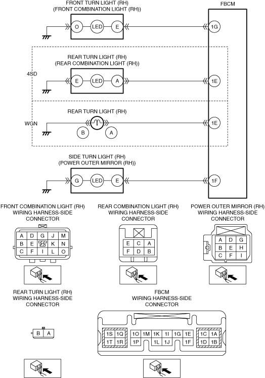
― Front turn light (RH)
― Side turn light (RH)
― Rear turn light (RH)
|
Yes
|
All lights do not flash or continue to be illuminated:
• Go to the next step.
Front turn light (RH) do not flash or continue to be illuminated:
• Go to Step 4.
Side turn light (RH) do not flash or continue to be illuminated:
• Go to Step 10.
Rear turn light (RH) do not flash or continue to be illuminated:
• Go to Step 16.
|
|
No
|
Go to Step 22.
|
|
3
|
INSPECT FRONT BODY CONTROL MODULE (FBCM) CONNECTOR
• Switch the ignition off.
• Disconnect the negative battery terminal.
• Disconnect the front body control module (FBCM) connector.
• Inspect the connector engagement and connection condition and inspect the terminals for damage, deformation, corrosion, or disconnection.
• Is the connector normal?
|
Yes
|
Go to Step 22.
|
|
No
|
Repair or replace the connector, then go to Step 22.
|
|
4
|
INSPECT FRONT COMBINATION LIGHT (RH) CONNECTOR
• Switch the ignition off.
• Disconnect the negative battery terminal.
• Disconnect the front combination light (RH) connector.
• Inspect the connector engagement and connection condition and inspect the terminals for damage, deformation, corrosion, or disconnection.
• Is the connector normal?
|
Yes
|
Go to the next step.
|
|
No
|
Repair or replace the connector, then go to Step 22.
|
|
5
|
INSPECT FOR OPEN CIRCUIT IN FRONT TURN LIGHT (RH) GROUND CIRCUIT
• Verify that the front combination light (RH) connector is disconnected.
• Inspect for continuity between front combination light (RH) terminal O (wiring harness-side) and body ground.
• Is there continuity?
|
Yes
|
Go to the next step.
|
|
No
|
Refer to the wiring diagram and verify whether or not there is a common connector between front combination light (RH) terminal O and body ground.
If there is a common connector:
• Determine the malfunctioning part by inspecting the common connector and the terminal for corrosion, damage, or pin disconnection, and the common wiring harness for an open circuit.
• Repair or replace the malfunctioning part.
If there is no common connector:
• Repair or replace the wiring harness which has an open circuit.
Go to Step 22.
|
|
6
|
INSPECT FRONT BODY CONTROL MODULE (FBCM) CONNECTOR
• Disconnect the front body control module (FBCM) connector.
• Inspect the connector engagement and connection condition and inspect the terminals for damage, deformation, corrosion, or disconnection.
• Is the connector normal?
|
Yes
|
Go to the next step.
|
|
No
|
Repair or replace the connector, then go to Step 22.
|
|
7
|
INSPECT FOR SHORT TO POWER SUPPLY IN FRONT TURN LIGHT (RH) CONTROL CIRCUIT
• Verify that the front combination light (RH) and front body control module (FBCM) connectors are disconnected.
• Reconnect the negative battery terminal.
• Switch the ignition ON (engine off or on).
• Measure the voltage at the front body control module (FBCM) terminal 1G (wiring harness-side).
• Is the voltage 0 V?
|
Yes
|
Go to the next step.
|
|
No
|
Refer to the wiring diagram and verify whether or not there is a common connector between front combination light (RH) terminal E and front body control module (FBCM) terminal 1G.
If there is a common connector:
• Determine the malfunctioning part by inspecting the common connector and the terminal for corrosion, damage, or pin disconnection, and the common wiring harness for a short to power supply.
• Repair or replace the malfunctioning part.
If there is no common connector:
• Repair or replace the wiring harness which has a short to power supply.
Go to Step 22.
|
|
8
|
INSPECT FOR OPEN CIRCUIT IN FRONT TURN LIGHT (RH) CONTROL CIRCUIT
• Verify that the front combination light (RH) and front body control module (FBCM) connectors are disconnected.
• Switch the ignition off.
• Disconnect the negative battery terminal.
• Inspect for continuity between front combination light (RH) terminal E (wiring harness-side) and front body control module (FBCM) terminal 1G (wiring harness-side).
• Is there continuity?
|
Yes
|
Go to Step 22.
|
|
No
|
Refer to the wiring diagram and verify whether or not there is a common connector between front combination light (RH) terminal E and front body control module (FBCM) terminal 1G.
If there is a common connector:
• Determine the malfunctioning part by inspecting the common connector and the terminal for corrosion, damage, or pin disconnection, and the common wiring harness for an open circuit.
• Repair or replace the malfunctioning part.
If there is no common connector:
• Repair or replace the wiring harness which has an open circuit.
Go to Step 22.
|
|
9
|
VERIFY IF MALFUNCTIONING LOCATION IS FRONT COMBINATION LIGHT (RH) DEPENDING ON REPEATABILITY
• Always reconnect all disconnected connectors.
• Reconnect the negative battery terminal.
• Clear the DTC for the front body control module (FBCM) using the M-MDS.
• Retrieve the front body control module (FBCM) DTCs using the M-MDS.
• Is the same Pending DTC present?
|
Yes
|
Replace the front combination light (RH), then go to Step 22.
|
|
No
|
Go to Step 23.
|
|
10
|
INSPECT POWER OUTER MIRROR (RH) CONNECTOR
• Switch the ignition off.
• Disconnect the negative battery terminal.
• Disconnect the power outer mirror (RH) connector.
• Inspect the connector engagement and connection condition and inspect the terminals for damage, deformation, corrosion, or disconnection.
• Is the connector normal?
|
Yes
|
Go to the next step.
|
|
No
|
Repair or replace the connector, then go to Step 22.
|
|
11
|
INSPECT FOR OPEN CIRCUIT IN SIDE TURN LIGHT (RH) GROUND CIRCUIT
• Verify that the power outer mirror (RH) connector is disconnected.
• Inspect for continuity between power outer mirror (RH) terminal G (wiring harness-side) and body ground.
• Is there continuity?
|
Yes
|
Go to the next step.
|
|
No
|
Refer to the wiring diagram and verify whether or not there is a common connector between power outer mirror (RH) terminal G and body ground.
If there is a common connector:
• Determine the malfunctioning part by inspecting the common connector and the terminal for corrosion, damage, or pin disconnection, and the common wiring harness for an open circuit.
• Repair or replace the malfunctioning part.
If there is no common connector:
• Repair or replace the wiring harness which has an open circuit.
Go to Step 22.
|
|
12
|
INSPECT SIDE TURN LIGHT (RH)
• Inspect the side turn light (RH).
• Is the side turn light (RH) normal?
|
Yes
|
Go to the next step.
|
|
No
|
Replace the power outer mirror (RH), then go to Step 22.
|
|
13
|
INSPECT FRONT BODY CONTROL MODULE (FBCM) CONNECTOR
• Disconnect the front body control module (FBCM) connector.
• Inspect the connector engagement and connection condition and inspect the terminals for damage, deformation, corrosion, or disconnection.
• Is the connector normal?
|
Yes
|
Go to the next step.
|
|
No
|
Repair or replace the connector, then go to Step 22.
|
|
14
|
INSPECT FOR SHORT TO POWER SUPPLY IN SIDE TURN LIGHT (RH) CONTROL CIRCUIT
• Verify that the power outer mirror (RH) and front body control module (FBCM) connectors are disconnected.
• Reconnect the negative battery terminal.
• Switch the ignition ON (engine off or on).
• Measure the voltage at the front body control module (FBCM) terminal 1F (wiring harness-side).
• Is the voltage 0 V?
|
Yes
|
Go to the next step.
|
|
No
|
Refer to the wiring diagram and verify whether or not there is a common connector between power outer mirror (RH) terminal E and front body control module (FBCM) terminal 1F.
If there is a common connector:
• Determine the malfunctioning part by inspecting the common connector and the terminal for corrosion, damage, or pin disconnection, and the common wiring harness for a short to power supply.
• Repair or replace the malfunctioning part.
If there is no common connector:
• Repair or replace the wiring harness which has a short to power supply.
Go to Step 22.
|
|
15
|
INSPECT FOR OPEN CIRCUIT IN SIDE TURN LIGHT (RH) CONTROL CIRCUIT
• Verify that the power outer mirror (RH) and front body control module (FBCM) connectors are disconnected.
• Switch the ignition off.
• Disconnect the negative battery terminal.
• Inspect for continuity between power outer mirror (RH) terminal E (wiring harness-side) and front body control module (FBCM) terminal 1F (wiring harness-side).
• Is there continuity?
|
Yes
|
Go to Step 22.
|
|
No
|
Refer to the wiring diagram and verify whether or not there is a common connector between power outer mirror (RH) terminal E and front body control module (FBCM) terminal 1F.
If there is a common connector:
• Determine the malfunctioning part by inspecting the common connector and the terminal for corrosion, damage, or pin disconnection, and the common wiring harness for an open circuit.
• Repair or replace the malfunctioning part.
If there is no common connector:
• Repair or replace the wiring harness which has an open circuit.
Go to Step 22.
|
|
16
|
INSPECT REAR COMBINATION LIGHT (RH) (4SD)/REAR TURN LIGHT (RH) (WGN) CONNECTOR
• Switch the ignition off.
• Disconnect the negative battery terminal.
• Disconnect the rear combination light (RH) connector. (4SD)
• Disconnect the rear turn light (RH) connector. (WGN)
• Inspect the connector engagement and connection condition and inspect the terminals for damage, deformation, corrosion, or disconnection.
• Is the connector normal?
|
Yes
|
Go to the next step.
|
|
No
|
Repair or replace the connector, then go to Step 22.
|
|
17
|
INSPECT FOR OPEN CIRCUIT IN REAR TURN LIGHT (RH) GROUND CIRCUIT
• Verify that the rear combination light (RH) connector is disconnected. (4SD)
• Verify that the rear turn light (RH) connector is disconnected. (WGN)
• Inspect for continuity between rear combination light (RH) terminal E (wiring harness-side) and body ground. (4SD)
• Inspect for continuity between rear turn light (RH) terminal B (wiring harness-side) and body ground. (WGN)
• Is there continuity?
|
Yes
|
Go to the next step.
|
|
No
|
Refer to the wiring diagram and verify whether or not there is a common connector between rear combination light (RH) terminal E and body ground. (4SD)
Refer to the wiring diagram and verify whether or not there is a common connector between rear turn light (RH) terminal B and body ground. (WGN)
If there is a common connector:
• Determine the malfunctioning part by inspecting the common connector and the terminal for corrosion, damage, or pin disconnection, and the common wiring harness for an open circuit.
• Repair or replace the malfunctioning part.
If there is no common connector:
• Repair or replace the wiring harness which has an open circuit.
Go to Step 22.
|
|
18
|
INSPECT FRONT BODY CONTROL MODULE (FBCM) CONNECTOR
• Disconnect the front body control module (FBCM) connector.
• Inspect the connector engagement and connection condition and inspect the terminals for damage, deformation, corrosion, or disconnection.
• Is the connector normal?
|
Yes
|
Go to the next step.
|
|
No
|
Repair or replace the connector, then go to Step 22.
|
|
19
|
INSPECT FOR SHORT TO POWER SUPPLY IN REAR TURN LIGHT (RH) CONTROL CIRCUIT
• Verify that the rear combination light (RH) and front body control module (FBCM) connectors are disconnected. (4SD)
• Verify that the rear turn light (RH) and front body control module (FBCM) connectors are disconnected. (WGN)
• Reconnect the negative battery terminal.
• Switch the ignition ON (engine off or on).
• Measure the voltage at the front body control module (FBCM) terminal 1E (wiring harness-side).
• Is the voltage 0 V?
|
Yes
|
Go to the next step.
|
|
No
|
Refer to the wiring diagram and verify whether or not there is a common connector between rear combination light (RH) terminal A and front body control module (FBCM) terminal 1E. (4SD)
Refer to the wiring diagram and verify whether or not there is a common connector between rear turn light (RH) terminal A and front body control module (FBCM) terminal 1E. (WGN)
If there is a common connector:
• Determine the malfunctioning part by inspecting the common connector and the terminal for corrosion, damage, or pin disconnection, and the common wiring harness for a short to power supply.
• Repair or replace the malfunctioning part.
If there is no common connector:
• Repair or replace the wiring harness which has a short to power supply.
Go to Step 22.
|
|
20
|
INSPECT FOR OPEN CIRCUIT IN REAR TURN LIGHT (RH) CONTROL CIRCUIT
• Verify that the rear combination light (RH) and front body control module (FBCM) connectors are disconnected. (4SD)
• Verify that the rear turn light (RH) and front body control module (FBCM) connectors are disconnected. (WGN)
• Switch the ignition off.
• Disconnect the negative battery terminal.
• Inspect for continuity between rear combination light (RH) terminal A (wiring harness-side) and front body control module (FBCM) terminal 1E (wiring harness-side). (4SD)
• Inspect for continuity between rear turn light (RH) terminal A (wiring harness-side) and front body control module (FBCM) terminal 1E (wiring harness-side). (WGN)
• Is there continuity?
|
Yes
|
Go to the next step.
|
|
No
|
Refer to the wiring diagram and verify whether or not there is a common connector between rear combination light (RH) terminal A and front body control module (FBCM) terminal 1E. (4SD)
Refer to the wiring diagram and verify whether or not there is a common connector between rear turn light (RH) terminal A and front body control module (FBCM) terminal 1E. (WGN)
If there is a common connector:
• Determine the malfunctioning part by inspecting the common connector and the terminal for corrosion, damage, or pin disconnection, and the common wiring harness for an open circuit.
• Repair or replace the malfunctioning part.
If there is no common connector:
• Repair or replace the wiring harness which has an open circuit.
Go to the next step.
|
|
21
|
VERIFY IF MALFUNCTIONING LOCATION IS REAR COMBINATION LIGHT (RH) (4SD)/REAR TURN LIGHT (RH) (WGN) DEPENDING ON REPEATABILITY
• Always reconnect all disconnected connectors.
• Reconnect the negative battery terminal.
• Clear the DTC for the front body control module (FBCM) using the M-MDS.
• Retrieve the front body control module (FBCM) DTCs using the M-MDS.
• Is the same Pending DTC present?
|
Yes
|
4SD:
• Replace the rear combination light (RH), then go to the next step.
WGN:
• Replace the rear turn light (RH), then go to the next step.
|
|
No
|
Go to Step 23.
|
|
22
|
VERIFY THAT REPAIRS HAVE BEEN COMPLETED
• Always reconnect all disconnected connectors.
• Reconnect the negative battery terminal.
• Clear the DTC for the front body control module (FBCM) using the M-MDS.
• Retrieve the front body control module (FBCM) DTCs using the M-MDS.
• Is the same Pending DTC present?
|
Yes
|
Repeat the inspection from Step 1.
• If the malfunction recurs, replace the front body control module (FBCM).
Go to the next step.
|
|
No
|
Go to the next step.
|
|
23
|
VERIFY IF OTHER DTCs DISPLAYED
• Are any other DTCs displayed?
|
Yes
|
Repair or replace the malfunctioning part according to the applicable DTC troubleshooting.
|
|
No
|
DTC troubleshooting completed.
|