 |
am6zzw00017202
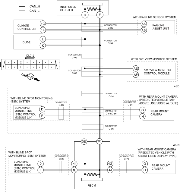
DETERMINING SHORT TO GROUND LOCATION (MS-CAN) [SKYACTIV-G 2.0/2.5, SKYACTIV-D 2.2 (MTX) (L.H.D.)]
id100238000900
System Wiring Diagram
am6zzw00017202
|
Determination Procedure
|
Step |
Inspection |
Action |
|
|---|---|---|---|
|
1
|
INSPECT FOR SHORT TO GROUND BETWEEN CONNECTOR C-35 AND REAR BODY CONTROL MODULE (RBCM)
• Disconnect the negative battery terminal.
• Disconnect connector C-35.
• Inspect for continuity at the following terminals:
• Is there continuity?
|
Yes
|
Go to Step 7.
|
|
No
|
Go to the next step.
|
||
|
2
|
INSPECT FOR SHORT TO GROUND BETWEEN CONNECTOR C-35 AND CLIMATE CONTROL UNIT
• Inspect for continuity at the following terminals:
• Is there continuity?
|
Yes
|
Go to the next step.
|
|
No
|
Go to Step 4.
|
||
|
3
|
INSPECT CAN LINE IN CLIMATE CONTROL UNIT FOR SHORT TO GROUND
• Disconnect the climate control unit connector.
• Inspect for continuity at the following terminals:
• Is there continuity?
|
Yes
|
Repair or replace the wiring harness between the climate control unit and connector C-35 because the wiring harness is shorted to ground.
|
|
No
|
Replace the climate control unit because there is a short to ground in the climate control unit.
|
||
|
4
|
INSPECT FOR SHORT TO GROUND BETWEEN CONNECTOR C-35 AND PARKING ASSIST UNIT
• Inspect for continuity at the following terminals:
• Is there continuity?
|
Yes
|
Go to the next step.
|
|
No
|
Go to Step 6.
|
||
|
5
|
INSPECT CAN LINE IN PARKING ASSIST UNIT FOR SHORT TO GROUND
• Disconnect the parking assist unit connector.
• Inspect for continuity at the following terminals:
• Is there continuity?
|
Yes
|
Repair or replace the wiring harness between the parking assist unit and connector C-35 because the wiring harness is shorted to ground.
|
|
No
|
Replace the parking assist unit because there is a short to ground in the parking assist unit.
|
||
|
6
|
INSPECT CAN LINE IN INSTRUMENT CLUSTER FOR SHORT TO GROUND
• Disconnect the instrument cluster connector.
• Inspect for continuity at the following terminals:
• Is there continuity?
|
Yes
|
Repair or replace the wiring harness between the instrument cluster and connector C-35 because the wiring harness is shorted to ground.
|
|
No
|
Replace the instrument cluster because there is a short to ground in the instrument cluster.
|
||
|
7
|
INSPECT FOR SHORT TO GROUND BETWEEN CONNECTOR C-35 AND CONNECTOR C-34
• Disconnect connector C-34.
• Connect connector C-35.
• Inspect for continuity at the following terminals:
• Is there continuity?
|
Yes
|
Repair or replace the wiring harness between connector C-35 and connector C-34 because the wiring harness is shorted to ground.
|
|
No
|
Go to the next step.
|
||
|
8
|
INSPECT FOR SHORT TO GROUND BETWEEN CONNECTOR C-34 AND DLC-2
• Inspect for continuity at the following terminals:
• Is there continuity?
|
Yes
|
Repair or replace the wiring harness between connector C-34 and DLC-2 because the wiring harness is shorted to ground.
|
|
No
|
Go to the next step.
|
||
|
9
|
INSPECT FOR SHORT TO GROUND BETWEEN CONNECTOR C-34 AND CONNECTOR C-09
• Disconnect connector C-09.
• Connect connector C-34.
• Inspect for continuity at the following terminals:
• Is there continuity?
|
Yes
|
Repair or replace the wiring harness between connector C-34 and connector C-09 because the wiring harness is shorted to ground.
|
|
No
|
Go to the next step.
|
||
|
10
|
INSPECT FOR SHORT TO GROUND BETWEEN CONNECTOR C-09 AND CONNECTOR C-63
• Disconnect connector C-63.
• Connect connector C-09.
• Inspect for continuity at the following terminals:
• Is there continuity?
|
Yes
|
Repair or replace the wiring harness between connector C-09 and connector C-63 because the wiring harness is shorted to ground.
|
|
No
|
Go to the next step.
|
||
|
11
|
INSPECT FOR SHORT TO GROUND BETWEEN 360° VIEW MONITOR CONTROL MODULE AND CONNECTOR C-63
• Inspect for continuity at the following terminals:
• Is there continuity?
|
Yes
|
Go to the next step.
|
|
No
|
• Go to Step 13.(with 4SD)
• Go to Step 23.(with WGN)
|
||
|
12
|
INSPECT CAN LINE IN 360° VIEW MONITOR CONTROL MODULE FOR SHORT TO GROUND
• Disconnect the 360° view monitor control module connector.
• Inspect for continuity at the following terminals:
• Is there continuity?
|
Yes
|
Repair or replace the wiring harness between the 360° view monitor control module and connector C-63 because the wiring harness is shorted to ground.
|
|
No
|
Replace the 360° view monitor control module because there is a short to ground in the 360° view monitor control module.
|
||
|
13
|
INSPECT FOR SHORT TO GROUND BETWEEN CONNECTOR C-63 AND CONNECTOR C-14
• Disconnect connector C-14.
• Connect connector C-63.
• Inspect for continuity at the following terminals:
• Is there continuity?
|
Yes
|
Repair or replace the wiring harness between connector C-63 and connector C-14 because the wiring harness is shorted to ground.
|
|
No
|
Go to the next step.
|
||
|
14
|
INSPECT FOR SHORT TO GROUND BETWEEN CONNECTOR C-14 AND CONNECTORS C-55, C-56
• Disconnect connectors C-55, C-56.
• Connect connector C-14.
• Inspect for continuity at the following terminals:
• Is there continuity?
|
Yes
|
Repair or replace the wiring harness between connectors C-55, C-56 and connector C-14 because the wiring harness is shorted to ground.
|
|
No
|
Go to the next step.
|
||
|
15
|
INSPECT FOR SHORT TO GROUND BETWEEN BLIND SPOT MONITORING (BSM) CONTROL MODULE (LH) AND CONNECTORS C-55, C-56
• Inspect for continuity at the following terminals:
• Is there continuity?
|
Yes
|
Go to the next step.
|
|
No
|
Go to Step 18.
|
||
|
16
|
INSPECT FOR SHORT TO GROUND BETWEEN BLIND SPOT MONITORING (BSM) CONTROL MODULE (LH) AND CONNECTOR C-23
• Disconnect connector C-23.
• Inspect for continuity at the following terminals:
• Is there continuity?
|
Yes
|
Repair or replace the wiring harness between connectors C-55, C-56 and connector C-23 because the wiring harness is shorted to ground.
|
|
No
|
Go to the next step.
|
||
|
17
|
INSPECT CAN LINE IN BLIND SPOT MONITORING (BSM) CONTROL MODULE (LH) FOR SHORT TO GROUND
• Disconnect the blind spot monitoring (BSM) control module (LH) connector.
• Inspect for continuity at the following terminals:
• Is there continuity?
|
Yes
|
Repair or replace the wiring harness between the blind spot monitoring (BSM) control module (LH) and connector C-23 because the wiring harness is shorted to ground.
|
|
No
|
Replace the blind spot monitoring (BSM) control module (LH) because there is a short to ground in the blind spot monitoring (BSM) control module (LH).
|
||
|
18
|
INSPECT FOR SHORT TO GROUND BETWEEN REAR MOUNT CAMERA AND CONNECTORS C-55,C-56
• Inspect for continuity at the following terminals:
• Is there continuity?
|
Yes
|
Go to the next step.
|
|
No
|
Go to Step 21.
|
||
|
19
|
INSPECT FOR SHORT TO GROUND BETWEEN REAR MOUNT CAMERA AND CONNECTOR C-21
• Disconnect connector C-21.
• Inspect for continuity at the following terminals:
• Is there continuity?
|
Yes
|
Go to the next step.
|
|
No
|
Repair or replace the wiring harness between the connectors C-55,C-56 and connector C-21 because the wiring harness is shorted to ground.
|
||
|
20
|
INSPECT CAN LINE IN REAR MOUNT CAMERA FOR SHORT TO GROUND
• Disconnect the rear mount camera connector.
• Inspect for continuity at the following terminals:
• Is there continuity?
|
Yes
|
Repair or replace the wiring harness between the rear mount camera and connector C-21 because the wiring harness is shorted to ground.
|
|
No
|
Replace the rear mount camera because there is a short to ground in the rear mount camera.
|
||
|
21
|
INSPECT FOR SHORT TO GROUND BETWEEN CONNECTOR C-06 AND CONNECTORS C-55,C-56
• Disconnect connector C-06.
• Connect connectors C-55,C-56.
• Inspect for continuity at the following terminals:
• Is there continuity?
|
Yes
|
Repair or replace the wiring harness between connectors C-55,C-56 and connector C-06 because the wiring harness is shorted to ground.
|
|
No
|
Go to the next step.
|
||
|
22
|
INSPECT FOR SHORT TO GROUND BETWEEN CONNECTOR C-06 AND REAR BODY CONTROL MODULE (RBCM)
• Disconnect the rear body control module (RBCM) connector.
• Inspect for continuity at the following terminals:
• Is there continuity?
|
Yes
|
Repair or replace the wiring harness between the rear body control module (RBCM) and connector C-06 because the wiring harness is shorted to ground.
|
|
No
|
Replace the rear body control module (RBCM) because there is a short to ground in the rear body control module (RBCM).
|
||
|
23
|
INSPECT FOR SHORT TO GROUND BETWEEN CONNECTOR C-63 AND REAR BODY CONTROL MODULE (RBCM)
• Disconnect the rear body control module (RBCM) connector.
• Connect connector C-63.
• Inspect for continuity at the following terminals:
• Is there continuity?
|
Yes
|
Repair or replace the wiring harness between the rear body control module (RBCM) and connector C-63 because the wiring harness is shorted to ground.
|
|
No
|
Go to the next step.
|
||
|
24
|
INSPECT FOR SHORT TO GROUND BETWEEN BLIND SPOT MONITORING (BSM) CONTROL MODULE (LH) AND REAR BODY CONTROL MODULE (RBCM)
• Inspect for continuity at the following terminals:
• Is there continuity?
|
Yes
|
Go to the next step.
|
|
No
|
Go to Step 27.
|
||
|
25
|
INSPECT FOR SHORT TO GROUND BETWEEN BLIND SPOT MONITORING (BSM) CONTROL MODULE (LH) AND CONNECTOR C-23
• Disconnect connector C-23.
• Inspect for continuity at the following terminals:
• Is there continuity?
|
Yes
|
Go to the next step.
|
|
No
|
Repair or replace the wiring harness between the rear body control module (RBCM) and connector C-23 because the wiring harness is shorted to ground.
|
||
|
26
|
INSPECT CAN LINE IN BLIND SPOT MONITORING (BSM) CONTROL MODULE (LH) FOR SHORT TO GROUND
• Disconnect the blind spot monitoring (BSM) control module (LH) connector.
• Inspect for continuity at the following terminals:
• Is there continuity?
|
Yes
|
Repair or replace the wiring harness between the blind spot monitoring (BSM) control module (LH) and connector C-23 because the wiring harness is shorted to ground.
|
|
No
|
Replace the blind spot monitoring (BSM) control module (LH) because there is a short to ground in the blind spot monitoring (BSM) control module (LH).
|
||
|
27
|
INSPECT FOR SHORT TO GROUND BETWEEN REAR MOUNT CAMERA AND REAR BODY CONTROL MODULE (RBCM)
• Inspect for continuity at the following terminals:
• Is there continuity?
|
Yes
|
Go to the next step.
|
|
No
|
Replace the rear body control module (RBCM) because there is a short to ground in the rear body control module (RBCM).
|
||
|
28
|
INSPECT FOR SHORT TO GROUND BETWEEN REAR MOUNT CAMERA AND CONNECTOR C-70
• Disconnect connector C-70.
• Inspect for continuity at the following terminals:
• Is there continuity?
|
Yes
|
Go to the next step.
|
|
No
|
Repair or replace the wiring harness between the rear body control module (RBCM) and connector C-70 because the wiring harness is shorted to ground.
|
||
|
29
|
INSPECT CAN LINE IN REAR MOUNT CAMERA FOR SHORT TO GROUND
• Disconnect the rear mount camera connector.
• Inspect for continuity at the following terminals:
• Is there continuity?
|
Yes
|
Repair or replace the wiring harness between the rear mount camera and connector C-70 because the wiring harness is shorted to ground.
|
|
No
|
Replace the rear mount camera because there is a short to ground in the rear mount camera.
|
||