 |
am6zzw00014049
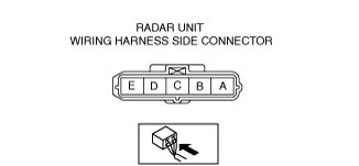
RADAR UNIT INSPECTION
id152000004700
1. Disconnect the negative battery terminal. (See NEGATIVE BATTERY TERMINAL DISCONNECTION/CONNECTION.)
2. Remove the following parts:
3. Connect the negative battery terminal. (See NEGATIVE BATTERY TERMINAL DISCONNECTION/CONNECTION.)
4. Verify that the voltages of each of the terminals are as indicated in the terminal voltage table (reference).
Terminal Voltage Table (Reference)
am6zzw00014049
|
|
Terminal |
Signal name |
Connected to |
Measurement conditions |
Voltage (V) |
Inspection item(s) |
|
|---|---|---|---|---|---|---|
|
A
|
—
|
—
|
—
|
—
|
—
|
|
|
B
|
GND
|
Body ground
|
Under any condition
|
1.0 or less
|
Related wiring harness
|
|
|
C
|
CAN_L
|
CAN system related module
|
Terminal used for communication therefore determination based on terminal voltage is not possible.
|
|||
|
D
|
CAN_H
|
CAN system related module
|
Terminal used for communication therefore determination based on terminal voltage is not possible.
|
|||
|
E
|
IG1
|
C/U IG1 15 A fuse
|
Ignition switched ON (engine off or ON)
|
B+
|
• C/U IG1 15 A fuse
• Related wiring harness
|
|
|
Ignition switched OFF (LOCK)
|
1.0 or less
|
|||||