 |
am6zzw00011959
SELECTOR LEVER REMOVAL/INSTALLATION
id051800802000
1. Disconnect the negative battery cable.
2. Remove battery and battery tray.
3. Remove the air cleaner component. (See INTAKE-AIR SYSTEM REMOVAL/INSTALLATION [LF, L3].)
4. Remove the console.
5. Remove the dashboard completely.
(See DASHBOARD REMOVAL/INSTALLATION.)
6. Remove the SAS control module.
(See SAS UNIT REMOVAL/INSTALLATION.)
7. Remove the A/C unit. (See A/C UNIT REMOVAL/INSTALLATION.)
8. Remove the rear heat duct. (See REAR HEAT DUCT REMOVAL/INSTALLATION.)
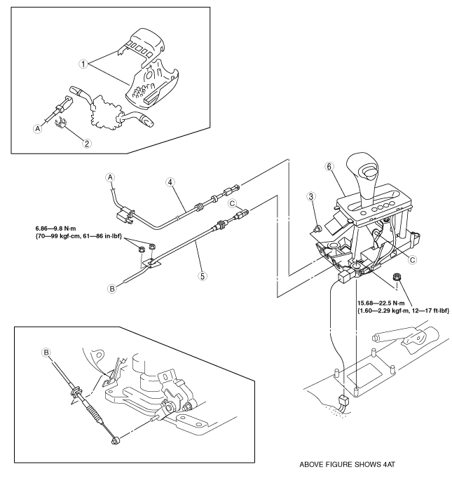
9. Remove in the order shown in the figure.
10. Remove the battery, battery tray and battery bracket.
11. Install in the reverse order of removal.
am6zzw00011959
|
|
1
|
Column cover (with key interlock)
|
|
2
|
Clip (with key interlock)
|
|
3
|
Clip (with key interlock)
|
|
4
|
Interlock cable (with key interlock)
|
|
5
|
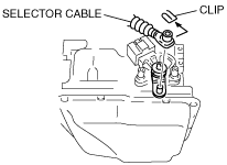
Selector cable
(See Selector Cable Removal Note.)
|
|
6
|
Selector lever
|
Selector Cable Removal Note
1. Remove the clip.
2. Remove the selector cable.
am6zzw00011960
|
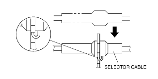
Selector Cable Installation Note
1. Install the selector cable to the selector lever securely.
2. Install the selector cable to the bracket securely.
am6zzw00011961
|
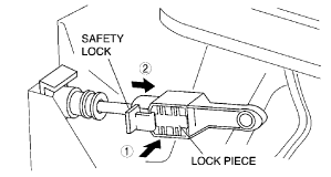
3. Verify that the selector lever is in P position.
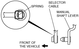
4. Lock the lock piece of the selector cable (selector lever side) in the order shown in the figure.
am6zzw00011962
|
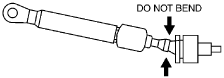
5. Verify that the manual shaft is in P position.
am6zzw00011963
|
am6zzw00011964
|
6. Install the selector lever to the manual shaft lever so that no load acts on the selector cable.
7. Confirm that the tip of the manual shaft lever projects out of the end of the selector cable.
8. Install the selector cable to the selector cable securely bracket.
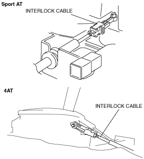
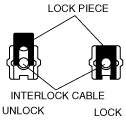
Interlock Cable Installation Note
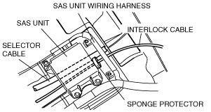
1. Install the interlock cable as shown in the figure.
am6zzw00011965
|
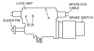
2. Push the snap pin (or a φ1.5 round bar or similar) into hole A by fully pushing in the slider pin.
chu0514w012
|
3. Push the snap pin into hole B and hole C of the lock unit until it passes through.
4. Disconnect the brake switch connector.
5. Remove the brake switch. (See BRAKE PEDAL REMOVAL/INSTALLATION.)
6. Install the new brake switch. (See BRAKE PEDAL REMOVAL/INSTALLATION.)
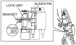
7. With the slider pin pressed, slide the lock unit to fix the lock unit hook into the bracket hole securely as shown in the figure.
am6zzw00011966
|
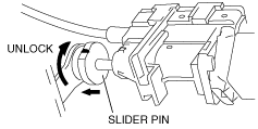
8. Rotate the slider pin to release the lock, and verify that it slides freely.
am6zzw00011967
|
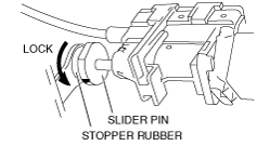
9. Pull the slider pin outward until it contacts the brake pedal stopper rubber and rotate the slider pin to lock.
am6zzw00011968
|
10. Verify that the shift the selector lever in P position.
11. Install the interlock cable end to the cam pin on the selector lever.
am6zzw00011969
|
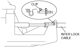
12. Fit the interlock cable in the U–groove in the selector lever base plate, and install the clip.
am6zzw00011970
|
13. Press the interlock cable lock piece in until it is locked.
am6zzw00011971
|
14. Remove the snap pin from the lock unit hole A, B and C.
chu0514w012
|
15. Connect the brake switch connector with the brake pedal released.
16. Turn the ignition switch to ON position.
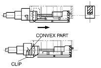
17. Install the interlock cable to the key cylinder.
18. Slide the outer casing to the key cylinder, and insert the clip over the convex part of the outer casing.
am6zzw00011972
|