 |
bgw2za00000152
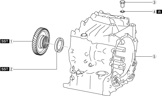
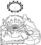
AUTOMATIC TRANSAXLE DISASSEMBLY
id051700660600
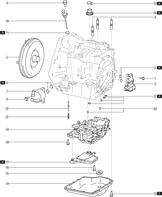
Structural View
Automatic transaxle 1
bgw2za00000152
|
|
1
|
3 bolts*1
|
|
2
|
Electric AT oil pump*1
|
|
3
|
O-ring*1
|
|
4
|
Stud bolt
|
|
5
|
Torque converter
|
|
6
|
3 bolts
|
|
7
|
Oil cooler
|
|
8
|
O-ring
|
|
9
|
Bolt
|
|
10
|
Dipstick
|
|
11
|
O-ring
|
|
12
|
Hose clamp
|
|
13
|
16 bolts
|
|
14
|
Oil pan
|
|
15
|
Magnet
|
|
16
|
2 bolts
|
|
17
|
Oil strainer
|
|
18
|
11 bolts
|
|
19
|
Control valve body
|
|
20
|
Dowel pin
|
|
21
|
Gasket
|
|
22
|
Spool valve spring*2
|
|
23
|
Spool valve*2
|
|
24
|
Oil seal
|
Automatic transaxle 2
bgw2za00000120
|
|
1
|
25 bolts
|
|
2
|
Converter housing
|
|
3
|
O-ring
|
|
4
|
O-ring
|
|
5
|
3 bolts
|
|
6
|
Baffle plate
|
|
7
|
Oil seal
|
|
8
|
Bearing race
|
|
9
|
Shim
|
|
10
|
Bearing race
|
|
11
|
Shim
|
Automatic transaxle 3
bgw2za00000153
|
|
1
|
Baffle plate
|
|
2
|
7 bolts
|
|
3
|
Oil pump
|
|
4
|
Thrust needle bearing
|
|
5
|
High clutch component and low clutch component
|
|
6
|
Turbine shaft
|
|
7
|
D-ring
|
|
8
|
Seal ring
|
|
9
|
Thrust needle bearing
|
|
10
|
High clutch hub
|
|
11
|
Thrust needle bearing
|
|
12
|
Low clutch hub
|
|
13
|
Thrust needle bearing
|
|
14
|
Ring gear and differential
|
|
15
|
Oil pipe
|
|
16
|
Secondary gear and output gear
|
|
17
|
2 bolts
|
|
18
|
Baffle plate
|
|
19
|
Oil seal
|
|
20
|
Bearing race
|
|
21
|
Shim
|
|
22
|
Bearing race
|
Automatic transaxle 4
bgw2za00000154
|
|
1
|
12 bolts
|
|
2
|
End cover component
|
|
3
|
O-ring
|
|
4
|
Shim
|
|
5
|
Thrust needle bearing
|
|
6
|
Reduction sun gear
|
|
7
|
Thrust needle bearing
|
|
8
|
Rear planetary gear
|
|
9
|
Rear sun gear
|
|
10
|
Front sun gear
|
|
11
|
Locknut
|
|
12
|
Front planetary gear
|
|
13
|
Snap ring
|
|
14
|
One-way clutch
|
|
15
|
Drive plate
|
|
16
|
Driven plate
|
|
17
|
Springs and retainer component
|
|
18
|
Low and reverse brake piston
|
Automatic transaxle 5
bgw2za00000155
|
|
1
|
Connector
|
|
2
|
Gasket
|
|
3
|
Gasket
|
|
4
|
Oil pipe
|
|
5
|
O-ring
|
|
6
|
2 bolts
|
|
7
|
Detent bracket component
|
|
8
|
Pawl return spring
|
|
9
|
Support actuator
|
|
10
|
Parking pawl pin
|
|
11
|
Parking rod component
|
|
12
|
Plug
|
|
13
|
Gasket
|
|
14
|
Parking pawl shaft
|
|
15
|
Parking pawl
|
|
16
|
Roll pin
|
|
17
|
Parking shift lever component
|
|
18
|
Parking assist lever component
|
|
19
|
Manual plate component
|
|
20
|
Oil seal
|
|
21
|
Washer
|
|
22
|
Connector bolt *
|
|
23
|
Gasket *
|
Automatic transaxle 6
bgw2za00000156
|
|
1
|
Primary gear
|
|
2
|
Angular contact ball bearing
|
|
3
|
Plug
|
|
4
|
Gasket
|
|
5
|
Transaxle case
|
Disassembly Procedure
1. Clean the outside of the transaxle. (See AUTOMATIC TRANSAXLE CLEANING.)
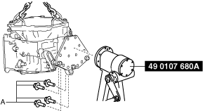
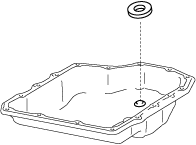
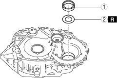
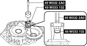
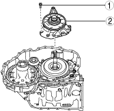
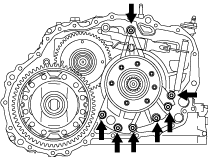
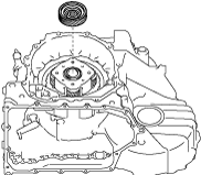
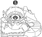
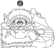
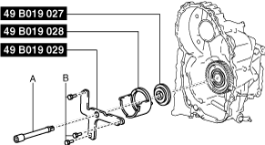
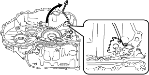
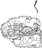
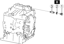
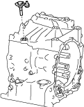
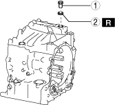
2. Remove the electric AT oil pump using the following procedure (only vehicles with i-stop).
bgw2za00000157
|
|
1
|
3 bolts
|
|
2
|
Electric AT oil pump
|
|
3
|
O-ring
|
bgw3ja00000101
|
bgw3ja00000102
|
bgw3ja00000103
|
bgw2za00000158
|
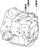
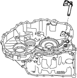
3. Remove the stud bolts.
bgw3ja00000105
|
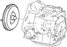
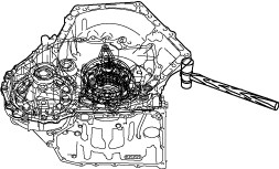
4. Remove the torque converter.
bgw3ja00000106
|
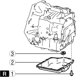
5. Remove the oil cooler in the order shown in the figure.
bgw2za00000159
|
|
1
|
Bolt
|
|
2
|
Oil cooler
|
|
3
|
O-ring
|
6. Remove the dipstick in the order shown in the figure.
bgw2za00000160
|
|
1
|
Bolt
|
|
2
|
Dipstick
|
|
3
|
O-ring
|
7. Remove the hose clamp.
bgw2za00000161
|
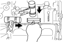
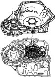
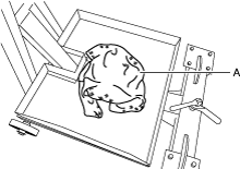
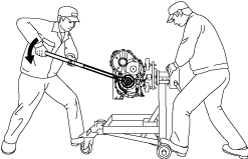
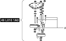
8. Install the transaxle to the SST (engine stand) using the following procedure:
bgw2za00000162
|
bgw2za00000163
|
bgw2za00000164
|
bgw2za00000165
|
bgw2za00000166
|
bgw2za00000167
|
bgw2za00000168
|
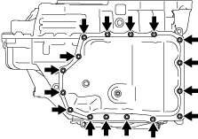
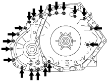
9. Remove the oil pan and magnet using the following procedure:
bgw2za00000169
|
|
1
|
16 bolts
|
|
2
|
Oil pan
|
|
3
|
Magnet
|
azzjjw00000423
|
azzjjw00000424
|
bgw3ja00000118
|
azzjjw00000426
|
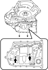
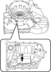
10. Remove the oil strainer in the order shown in the figure.
bgw2za00000170
|
|
1
|
Bolt
|
|
2
|
Oil strainer
|
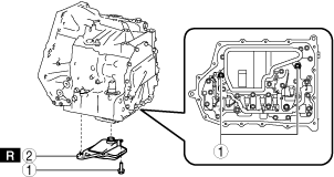
11. Remove the control valve body using the following procedure:
bgw2za00000171
|
|
1
|
11 bolts
|
|
2
|
Control valve body
|
|
3
|
Dowel pin
|
|
4
|
Gasket
|
|
5
|
Spool valve spring*
|
|
6
|
Spool valve*
|
azzjjw00000429
|
bgw3ja00000121
|
azzjjw00000431
|
bgw3ja00000122
|
bgw2za00000172
|
bgw3ja00000124
|
bgw3ja00000125
|
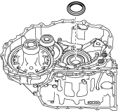
12. Remove the oil seal.
bgw2za00000173
|
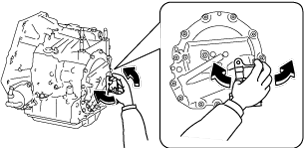
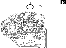
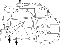
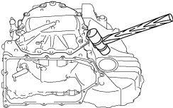
13. Remove the converter housing using the following procedure:
bgw2za00000174
|
|
1
|
25 bolts
|
|
2
|
Converter housing
|
|
3
|
O-ring (oil pump)
|
|
4
|
O-ring (oil cooler oil passage)
|
bgw3ja00000128
|
bgw3ja00000129
|
bgw3ja00000130
|
bgw3ja00000131
|
bgw2za00000175
|
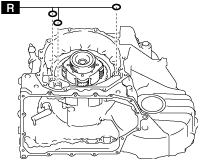
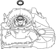
14. Remove the accessories from the converter housing using the following procedure:
bgw3ja00000133
|
|
1
|
Bolt
|
|
2
|
Baffle plate
|
bgw2za00000176
|
bgw3ja00000135
|
bgw2za00000177
|
|
1
|
Bearing race
|
|
2
|
Shim
|
bgw2za00000178
|
bgw2za00000179
|
bgw2za00000180
|
|
1
|
Bearing race
|
|
2
|
Shim
|
bgw2za00000178
|
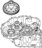
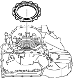
15. Remove the baffle plate.
bgw3ja00000140
|
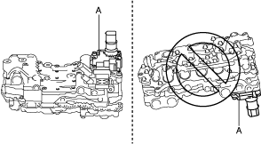
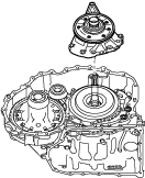
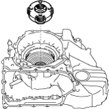
16. Remove the oil pump using the following procedure:
bgw3ja00000141
|
|
1
|
7 bolts
|
|
2
|
Oil pump
|
bgw3ja00000142
|
bgw3ja00000143
|
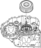
17. Remove the thrust needle bearing.
bgw3ja00000144
|
18. Remove the high clutch component and low clutch component.
bgw3ja00000145
|
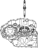
19. Remove the turbine shaft.
bgw3ja00000146
|
20. Remove the D-ring and seal rings from the turbine shaft using the procedure in the figure:
bgw2za00000181
|
|
1
|
D-ring
|
|
2
|
Seal ring
|
21. Remove the thrust needle bearing.
bgw3ja00000147
|
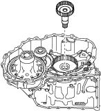
22. Remove the high clutch hub.
bgw3ja00000148
|
23. Remove the thrust needle bearing.
bgw3ja00000149
|
24. Remove the low clutch hub.
bgw3ja00000150
|
25. Remove the thrust needle bearing.
bgw3ja00000151
|
26. Remove the ring gear and differential.
bgw3ja00000152
|
27. Remove the oil pipe.
bgw3ja00000153
|
28. Remove the secondary gear and output gear.
bgw3ja00000154
|
29. Remove the baffle plate using the procedure shown in the figure.
bgw2za00000182
|
|
1
|
Bolt
|
|
2
|
Baffle plate
|
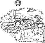
30. Remove the oil seal.
bgw2za00000183
|
31. Remove the bearing race and shim using the following procedure:
azzjjw00000465
|
bgw3ja00000156
|
bgw2za00000184
|
|
1
|
Bearing race
|
|
2
|
Shim
|
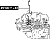
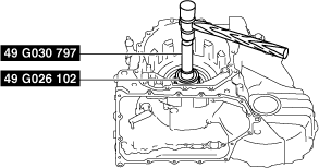
32. Remove the bearing race using the SST.
bgw3ja00000158
|
bgw3ja00000159
|
33. Remove end cover component using the following procedure:
bgw2za00000185
|
|
1
|
12 bolts
|
|
2
|
End cover component
|
|
3
|
O-ring
|
bgw3ja00000160
|
bgw3ja00000161
|
azzjjw00000473
|
bgw3ja00000162
|
bgw2za00000208
|
34. Remove the shim.
bgw3ja00000164
|
35. Remove the thrust needle bearing.
bgw3ja00000165
|
36. Remove the reduction sun gear.
bgw3ja00000166
|
37. Remove the thrust needle bearing.
bgw3ja00000167
|
38. Remove the rear planetary gear.
bgw3ja00000168
|
39. Remove the rear sun gear.
bgw3ja00000169
|
40. Remove the front sun gear.
bgw3ja00000170
|
41. Inspect the transaxle case, primary gear, and the angular contact ball bearing using the following procedure:
bgw3ja00000171
|
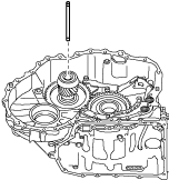
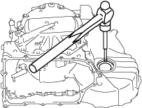
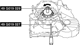
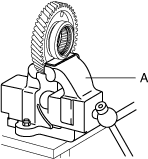
42. Remove the locknut using the following procedure:
bgw3ja00000172
|
bgw2za00000186
|
bgw2za00000187
|
azzjjw00000487
|
bgw2za00000186
|
bgw2za00000188
|
43. Remove the front planetary gear.
bgw3ja00000176
|
44. Perform a simple inspection of the low and reverse brake using the following procedure:
azzjjw00000490
|
45. Remove the snap ring using the following procedure:
bgw2za00000189
|
bgw2za00000190
|
bgw2za00000191
|
bgw3ja00000180
|
bgw2za00000192
|
bgw2za00000189
|
46. Remove the one-way clutch.
azzjjw00000496
|
47. Remove the drive plates and driven plates.
bgw3ja00000182
|
48. Remove the springs and retainer component.
azzjjw00000498
|
49. Remove the low and reverse brake piston using the following procedure:
azzjjw00000499
|
azzjjw00000500
|
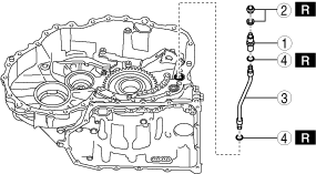
50. Remove the connector, gaskets, oil pipe, and the O-rings in the order shown in the figure.
bgw2za00000193
|
|
1
|
Connector
|
|
2
|
Gasket
|
|
3
|
Oil pipe
|
|
4
|
O-ring
|
51. Remove the detent bracket component in the order shown in the figure.
bgw3ja00000184
|
|
1
|
Bolt
|
|
2
|
Detent bracket component
|
52. Remove the pawl return springs.
bgw3ja00000185
|
53. Remove the support actuator.
bgw3ja00000186
|
54. Remove the parking pawl pin.
bgw3ja00000187
|
55. Remove the parking rod component using the following procedure:
bgw3ja00000188
|
bgw3ja00000189
|
56. Remove the parking pawl shaft in the order shown in the figure.
bgw2za00000194
|
|
1
|
Plug
|
|
2
|
Gasket
|
|
3
|
Parking pawl shaft
|
57. Remove the parking pawl.
bgw3ja00000190
|
58. Remove the roll pins shown in the figure using a pin punch.
bgw3ja00000191
|
bgw3ja00000192
|
59. Remove the parking shift lever component.
azzjjw00000512
|
60. Remove the parking assist lever component.
bgw3ja00000193
|
61. Remove the manual plate component.
bgw3ja00000194
|
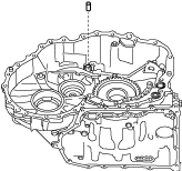
62. Remove the oil seal.
bgw2za00000195
|
63. Remove the washer.
azzjjw00000516
|
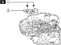
64. Remove the connector bolts and gaskets using the procedure shown in the figure (only vehicles with oil cooler No.2).
bgw2za00000196
|
|
1
|
Connector bolt
|
|
2
|
Gasket
|
65. Perform the following procedure only if there is a malfunction found in the Step 41 inspection.
azzjjw00000465
|
bgw2za00000197
|
bgw3ja00000196
|
azzjjw00001205
|
azzjjw00001206
|
bgw2za00000198
|
bgw2za00000199
|
azzjjw00001208
|
azzjjw00000917
|
|
1
|
Plug
|
|
2
|
Gasket
|
66. Remove the SST from the transaxle case using the following procedure:
azzjjw00000521
|
bgw2za00000200
|
bgw2za00000201
|
bgw2za00000202
|
67. Disassemble the parts in the following order.
68. Clean away the remaining silicone sealant on the transaxle case, converter housing, end cover, oil pan, and the electric AT oil pump*.
69. Clean the disassembled parts. (See AUTOMATIC TRANSAXLE CLEANING.)
70. Perform the following inspection and replace a malfunctioning part with a new one.