 |
am6zzw00013870
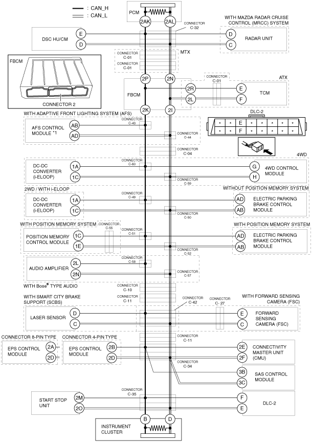
DETERMINING SHORT BETWEEN CIRCUITS LOCATION (HS-CAN) [SKYACTIV-D 2.2 (R.H.D.)]
id100206000800
System wiring diagram
am6zzw00013870
|
Determination Procedure
|
Step |
Inspection |
Action |
|
|---|---|---|---|
|
1
|
INSPECT BETWEEN FRONT BODY CONTROL MODULE (FBCM) AND INSTRUMENT CLUSTER FOR SHORT BETWEEN CIRCUITS
• Disconnect the negative battery cable.
• Disconnect connector 2 which has front body control module (FBCM) terminals 2K and 2I.
• Connect the negative battery cable.
• Switch the ignition ON (engine off).
• Measure the voltage at DLC-2 terminals F and E.
• Is the voltage at DLC-2 terminals F and E the same?
|
Yes
|
Go to Step 6.
|
|
No
|
• Go to the next step. (ATX)
• Go to Step 5. (MTX)
|
||
|
2
|
INSPECT BETWEEN TCM AND FRONT BODY CONTROL MODULE (FBCM) FOR SHORT BETWEEN CIRCUITS
• Switch the ignition off (LOCK).
• Disconnect the negative battery cable.
• Inspect for continuity between TCM terminals E and F.
• Is there continuity?
|
Yes
|
Go to the next step.
|
|
No
|
Go to Step 5.
|
||
|
3
|
INSPECT BETWEEN TCM AND CONNECTOR C-01 FOR SHORT BETWEEN CIRCUITS
• Disconnect the connector C-01.
• Inspect for continuity between TCM terminals E and F.
• Is there continuity?
|
Yes
|
Go to the next step.
|
|
No
|
Repair or replace the wiring harness between the front body control module (FBCM) and connector C-01 because the wiring harness is shorted between circuits.
|
||
|
4
|
INSPECT TCM FOR SHORT BETWEEN CIRCUITS
• Disconnect the TCM connector.
• Inspect for continuity between TCM terminals E and F (wiring harness side).
• Is there continuity?
|
Yes
|
Repair or replace the wiring harness between the TCM and connector C-01 because the wiring harness is shorted between circuits.
|
|
No
|
Replace the TCM because there is a short between circuits in the TCM.
|
||
|
5
|
INSPECT FRONT BODY CONTROL MODULE (FBCM) FOR SHORT BETWEEN CIRCUITS
• Switch the ignition off (LOCK).
• Disconnect the negative battery cable.
• Inspect for continuity between front body control module (FBCM) terminals 2K and 2I.
• Is there continuity?
|
Yes
|
Replace the front body control module (FBCM) because there is a short between circuits in the front body control module (FBCM).
|
|
No
|
• Go to Step 50. (ATX)
• Go to Step 51. (MTX)
|
||
|
6
|
INSPECT BETWEEN CONNECTORS C-43 AND C-44 AND INSTRUMENT CLUSTER FOR SHORT BETWEEN CIRCUITS
• Switch the ignition off (LOCK).
• Disconnect the negative battery cable.
• Disconnect connectors C-43 and C-44.
• Connect the negative battery cable.
• Switch the ignition ON (engine off).
• Measure the voltage at DLC-2 terminals F and E.
• Is the voltage at DLC-2 terminals F and E the same?
|
Yes
|
Go to Step 9.
|
|
No
|
Go to the next step.
|
||
|
7
|
INSPECT BETWEEN AFS CONTROL MODULE AND ONNECTORS C-43 AND C-44 FOR SHORT BETWEEN CIRCUITS
• Switch the ignition off (LOCK).
• Disconnect the negative battery cable.
• Inspect for continuity between AFS control module terminals AB and AD.
• Is there continuity?
|
Yes
|
Go to the next step.
|
|
No
|
Repair or replace the wiring harness between front body control module (FBCM) and connectors C-43 and C-44 because the wiring harness is shorted between circuits.
|
||
|
8
|
INSPECT AFS CONTROL MODULE FOR SHORT BETWEEN CIRCUITS
• Disconnect the AFS control module connector.
• Inspect for continuity between AFS control module terminals AB and AD (wiring harness side).
• Is there continuity?
|
Yes
|
Repair or replace the wiring harness between the AFS control module and connectors C-43 and C-44 because the wiring harness is shorted between circuits.
|
|
No
|
Replace the AFS control module because there is a short between circuits in the AFS control module.
|
||
|
9
|
INSPECT BETWEEN CONNECTOR C-04 AND INSTRUMENT CLUSTER FOR SHORT BETWEEN CIRCUITS
• Switch the ignition off (LOCK).
• Disconnect the negative battery cable.
• Disconnect connector C-04.
• Connect the negative battery cable.
• Switch the ignition ON (engine off).
• Measure the voltage at DLC-2 terminals F and E.
• Is the voltage at DLC-2 terminals F and E the same?
|
Yes
|
• Go to the next step. (4WD)
• Go to Step 15. (2WD)
|
|
No
|
Repair or replace the wiring harness between connectors C-43 and C-44 and connector C-04 because the wiring harness is shorted between circuits.
|
||
|
10
|
INSPECT BETWEEN CONNECTORS C-60 AND C-59 AND INSTRUMENT CLUSTER FOR SHORT BETWEEN CIRCUITS
• Switch the ignition off (LOCK).
• Disconnect the negative battery cable.
• Disconnect connectors C-60 and C-59.
• Connect the negative battery cable.
• Switch the ignition ON (engine off).
• Measure the voltage at DLC-2 terminals F and E.
• Is the voltage at DLC-2 terminals F and E the same?
|
Yes
|
Go to Step 15.
|
|
No
|
Go to the next step.
|
||
|
11
|
INSPECT BETWEEN DC-DC CONVERTER (i-ELOOP) AND CONNECTORS C-60 AND C-59 FOR SHORT BETWEEN CIRCUITS
• Inspect for continuity between DC-DC converter (i-ELOOP) terminals 1A and 1C.
• Is there continuity?
|
Yes
|
Go to the next step.
|
|
No
|
Go to Step 13.
|
||
|
12
|
INSPECT DC-DC CONVERTER (i-ELOOP) FOR SHORT BETWEEN CIRCUITS
• Disconnect the DC-DC converter (i-ELOOP) connector.
• Inspect for continuity between DC-DC converter (i-ELOOP) terminals 1A and 1C (wiring harness side).
• Is there continuity?
|
Yes
|
Repair or replace the wiring harness between the DC-DC converter (i-ELOOP) and connectors C-60 and C-59 because the wiring harness is shorted between circuits.
|
|
No
|
Replace the DC-DC converter (i-ELOOP) because there is a short between circuits in the DC-DC converter (i-ELOOP).
|
||
|
13
|
INSPECT BETWEEN 4WD CONTROL MODULE AND CONNECTORS C-60 AND C-59 FOR SHORT BETWEEN CIRCUITS
• Inspect for continuity between 4WD control module terminals G and H.
• Is there continuity?
|
Yes
|
Go to the next step.
|
|
No
|
Repair or replace the wiring harness between connector C-04 and connectors C-60 and C-59 because the wiring harness is shorted between circuits.
|
||
|
14
|
INSPECT 4WD CONTROL MODULE FOR SHORT BETWEEN CIRCUITS
• Disconnect the 4WD control module connector.
• Inspect for continuity between 4WD control module terminals G and H (wiring harness side).
• Is there continuity?
|
Yes
|
Repair or replace the wiring harness between the 4WD control module and connectors C-60 and C-59 because the wiring harness is shorted between circuits.
|
|
No
|
Replace the 4WD control module because there is a short between circuits in the 4WD control module.
|
||
|
15
|
INSPECT BETWEEN CONNECTORS C-49 AND C-50 AND INSTRUMENT CLUSTER FOR SHORT BETWEEN CIRCUITS
• Switch the ignition off (LOCK).
• Disconnect the negative battery cable.
• Disconnect connectors C-49 and C-50.
• Connect the negative battery cable.
• Switch the ignition ON (engine off).
• Measure the voltage at DLC-2 terminals F and E.
• Is the voltage at DLC-2 terminals F and E the same?
|
Yes
|
Go to Step 20.
|
|
No
|
• Repair or replace the wiring harness between connectors C-60 and C-59 and connectors C-49 and C-50 because the wiring harness is shorted between circuits. (4WD and with position memory system)
• Go to Step 18. (4WD and without position memory system)
• Go to the next step. (2WD)
|
||
|
16
|
INSPECT BETWEEN DC-DC CONVERTER (i-ELOOP) AND CONNECTORS C-49 AND C-50 FOR SHORT BETWEEN CIRCUITS
• Inspect for continuity between DC-DC converter (i-ELOOP) terminals 1A and 1C.
• Is there continuity?
|
Yes
|
Go to the next step.
|
|
No
|
• Repair or replace the wiring harness between connector C-04 and connectors C-49 and C-50 because the wiring harness is shorted between circuits. (with position memory system)
• Go to Step 18. (without position memory system)
|
||
|
17
|
INSPECT DC-DC CONVERTER (i-ELOOP) FOR SHORT BETWEEN CIRCUITS
• Disconnect the DC-DC converter (i-ELOOP) connector.
• Inspect for continuity between DC-DC converter (i-ELOOP) terminals 1A and 1C (wiring harness side).
• Is there continuity?
|
Yes
|
Repair or replace the wiring harness between the DC-DC converter (i-ELOOP) and connectors C-49 and C-50 because the wiring harness is shorted between circuits.
|
|
No
|
Replace the DC-DC converter (i-ELOOP) because there is a short between circuits in the DC-DC converter (i-ELOOP).
|
||
|
18
|
INSPECT BETWEEN ELECTRIC PARKING BRAKE CONTROL MODULE AND CONNECTORS C-49 AND C-50 FOR SHORT BETWEEN CIRCUITS
• Switch the ignition off (LOCK).
• Disconnect the negative battery cable.
• Inspect for continuity between electric parking brake control module terminals AD and AB.
• Is there continuity?
|
Yes
|
Go to the next step.
|
|
No
|
• Repair or replace the wiring harness between connectors C-60 and C-59 and connectors C-49 and C-50 because the wiring harness is shorted between circuits. (4WD)
• Repair or replace the wiring harness between connector C-04 and connectors C-49 and C-50 because the wiring harness is shorted between circuits. (2WD)
|
||
|
19
|
INSPECT ELECTRIC PARKING BRAKE CONTROL MODULE FOR SHORT BETWEEN CIRCUITS
• Disconnect the electric parking brake control module connector.
• Inspect for continuity between electric parking brake control module terminals AD and AB (wiring harness side).
• Is there continuity?
|
Yes
|
Repair or replace the wiring harness between the electric parking brake control module and connectors C-49 and C-50 because the wiring harness is shorted between circuits.
|
|
No
|
Replace the electric parking brake control module because there is a short between circuits in the electric parking brake control module.
|
||
|
20
|
INSPECT BETWEEN CONNECTORS C-51 AND C-52 AND INSTRUMENT CLUSTER FOR SHORT BETWEEN CIRCUITS
• Switch the ignition off (LOCK).
• Disconnect the negative battery cable.
• Disconnect connectors C-51 and C-52.
• Connect the negative battery cable.
• Switch the ignition ON (engine off).
• Measure the voltage at DLC-2 terminals F and E.
• Is the voltage at DLC-2 terminals F and E the same?
|
Yes
|
Go to Step 26.
|
|
No
|
• Go to the next step. (with position memory system)
• Repair or replace the wiring harness between connectors C-49 and C-50 and connectors C-51 and C-52 because the wiring harness is shorted between circuits. (without position memory system)
|
||
|
21
|
INSPECT BETWEEN POSITION MEMORY CONTROL MODULE AND CONNECTORS C-51 AND C-52 FOR SHORT BETWEEN CIRCUITS
• Switch the ignition off (LOCK).
• Disconnect the negative battery cable.
• Inspect for continuity between position memory control module terminals 1C and 1E.
• Is there continuity?
|
Yes
|
Go to the next step.
|
|
No
|
Go to Step 24.
|
||
|
22
|
INSPECT BETWEEN CONNECTORS C-51 AND C-52 AND CONNECTOR C-55 FOR SHORT BETWEEN CIRCUITS
• Disconnect connector C-55.
• Inspect for continuity between position memory control module terminals 1C and 1E.
• Is there continuity?
|
Yes
|
Go to the next step.
|
|
No
|
Repair or replace the wiring harness between connectors C-51 and C-52 and connector C-55 because the wiring harness is shorted between circuits.
|
||
|
23
|
INSPECT POSITION MEMORY CONTROL MODULE FOR SHORT BETWEEN CIRCUITS
• Disconnect the position memory control module connector.
• Inspect for continuity between position memory control module terminals 1C and 1E (wiring harness side).
• Is there continuity?
|
Yes
|
Repair or replace the wiring harness between the position memory control module and connector C-55 because the wiring harness is shorted between circuits.
|
|
No
|
Replace the position memory control module because there is a short between circuits in the position memory control module.
|
||
|
24
|
INSPECT BETWEEN ELECTRIC PARKING BRAKE CONTROL MODULE AND CONNECTORS C-51 AND C-52 FOR SHORT BETWEEN CIRCUITS
• Switch the ignition off (LOCK).
• Disconnect the negative battery cable.
• Inspect for continuity between electric parking brake control module terminals AD and AB.
• Is there continuity?
|
Yes
|
Go to the next step.
|
|
No
|
Repair or replace the wiring harness between connectors C-49 and C-50 and connectors C-51 and C-52 because the wiring harness is shorted between circuits.
|
||
|
25
|
INSPECT ELECTRIC PARKING BRAKE CONTROL MODULE FOR SHORT BETWEEN CIRCUITS
• Disconnect the electric parking brake control module connector.
• Inspect for continuity between electric parking brake control module terminals AD and AB (wiring harness side).
• Is there continuity?
|
Yes
|
Repair or replace the wiring harness between the electric parking brake control module and connectors C-51 and C-52 because the wiring harness is shorted between circuits.
|
|
No
|
Replace the electric parking brake control module because there is a short between circuits in the electric parking brake control module.
|
||
|
26
|
INSPECT BETWEEN CONNECTORS C-58 AND C-57 AND INSTRUMENT CLUSTER FOR SHORT BETWEEN CIRCUITS
• Switch the ignition off (LOCK).
• Disconnect the negative battery cable.
• Disconnect connectors C-58 and C-57.
• Connect the negative battery cable.
• Switch the ignition ON (engine off).
• Measure the voltage at DLC-2 terminals F and E.
• Is the voltage at DLC-2 terminals F and E the same?
|
Yes
|
Go to Step 29.
|
|
No
|
Go to the next step.
|
||
|
27
|
INSPECT BETWEEN AUDIO AMPLIFIER AND CONNECTORS C-58 AND C-57 FOR SHORT BETWEEN CIRCUITS
• Switch the ignition off (LOCK).
• Disconnect the negative battery cable.
• Inspect for continuity between audio amplifier terminals 2L and 2N.
• Is there continuity?
|
Yes
|
Go to the next step.
|
|
No
|
Repair or replace the wiring harness between connectors C-51 and C-52 and connectors C-58 and C-57 because the wiring harness is shorted between circuits.
|
||
|
28
|
INSPECT AUDIO AMPLIFIER FOR SHORT BETWEEN CIRCUITS
• Disconnect the audio amplifier connector.
• Inspect for continuity between audio amplifier terminals 2L and 2N (wiring harness side).
• Is there continuity?
|
Yes
|
Repair or replace the wiring harness between the audio amplifier and connectors C-58 and C-57 because the wiring harness is shorted between circuits.
|
|
No
|
Replace the audio amplifier because there is a short between circuits in the audio amplifier.
|
||
|
29
|
INSPECT BETWEEN CONNECTOR C-10 AND INSTRUMENT CLUSTER FOR SHORT BETWEEN CIRCUITS
• Switch the ignition off (LOCK).
• Disconnect the negative battery cable.
• Disconnect connector C-10.
• Connect the negative battery cable.
• Switch the ignition ON (engine off).
• Measure the voltage at DLC-2 terminals F and E.
• Is the voltage at DLC-2 terminals F and E the same?
|
Yes
|
Go to the next step.
|
|
No
|
Repair or replace the wiring harness between connectors C-58 and C-57 and connector C-10 because the wiring harness is shorted between circuits.
|
||
|
30
|
INSPECT BETWEEN CONNECTOR C-10 AND CONNECTOR C-11 FOR SHORT BETWEEN CIRCUITS
• Switch the ignition off (LOCK).
• Disconnect the negative battery cable.
• Disconnect connector C-11.
• Connect connector C-10.
• Connect connectors C-58 and C-57.
• Connect connectors C-51 and C-52.
• Connect connectors C-49 and C-50.
• Connect connectors C-60 and C-59.
• Connect connector C-04.
• Connect connectors C-43 and C-44.
• Connect the negative battery cable.
• Switch the ignition ON (engine off).
• Measure the voltage at front body control module (FBCM) terminals 2K and 2I (wiring harness side).
• Is the voltage at front body control module (FBCM) terminals 2K and 2I (wiring harness side) the same?
|
Yes
|
Repair or replace the wiring harness between connector C-10 and connector C-11 because the wiring harness is shorted between circuits.
|
|
No
|
Go to the next step.
|
||
|
31
|
INSPECT BETWEEN CONNECTOR C-11 AND INSTRUMENT CLUSTER FOR SHORT BETWEEN CIRCUITS
• Measure the voltage at DLC-2 terminals F and E.
• Is the voltage at DLC-2 terminals F and E the same?
|
Yes
|
Go to Step 38.
|
|
No
|
Go to the next step.
|
||
|
32
|
INSPECT BETWEEN CONNECTOR C-42 AND CONNECTOR C-11 FOR SHORT BETWEEN CIRCUITS
• Switch the ignition off (LOCK).
• Disconnect the negative battery cable.
• Disconnect connector C-42.
• Connect connector C-11.
• Connect the negative battery cable.
• Switch the ignition ON (engine off).
• Measure the voltage at DLC-2 terminals F and E.
• Is the voltage at DLC-2 terminals F and E the same?
|
Yes
|
Repair or replace the wiring harness between connector C-42 and connector C-11 because the wiring harness is shorted between circuits.
|
|
No
|
Go to the next step.
|
||
|
33
|
INSPECT BETWEEN LASER SENSOR AND CONNECTOR C-42 FOR SHORT BETWEEN CIRCUITS
• Switch the ignition off (LOCK).
• Disconnect the negative battery cable.
• Inspect for continuity between laser sensor terminals D and C.
• Is there continuity?
|
Yes
|
Go to the next step.
|
|
No
|
Go to Step 35.
|
||
|
34
|
INSPECT LASER SENSOR FOR SHORT BETWEEN CIRCUITS
• Disconnect the laser sensor connector.
• Inspect for continuity between laser sensor terminals D and C (wiring harness side).
• Is there continuity?
|
Yes
|
Repair or replace the wiring harness between the laser sensor and connector C-42 because the wiring harness is shorted between circuits.
|
|
No
|
Replace the laser sensor because there is a short between circuits in the laser sensor.
|
||
|
35
|
INSPECT BETWEEN FORWARD SENSING CAMERA (FSC) AND CONNECTOR C-42 FOR SHORT BETWEEN CIRCUITS
• Inspect for continuity between forward sensing camera (FSC) terminals E and C.
• Is there continuity?
|
Yes
|
Go to the next step.
|
|
No
|
Repair or replace the wiring harness between connector C-11 and connector C-42 because the wiring harness is shorted between circuits.
|
||
|
36
|
INSPECT BETWEEN CONNECTOR C-42 AND CONNECTOR C-27 FOR SHORT BETWEEN CIRCUITS
• Disconnect connector C-27.
• Inspect for continuity between forward sensing camera (FSC) terminals E and C.
• Is there continuity?
|
Yes
|
Go to the next step.
|
|
No
|
Repair or replace the wiring harness between connector C-42 and connector C-27 because the wiring harness is shorted between circuits.
|
||
|
37
|
INSPECT FORWARD SENSING CAMERA (FSC) FOR SHORT BETWEEN CIRCUITS
• Disconnect the forward sensing camera (FSC) connector.
• Inspect for continuity between forward sensing camera (FSC) terminals E and C (wiring harness side).
• Is there continuity?
|
Yes
|
Repair or replace the wiring harness between the forward sensing camera (FSC) and connector C-27 because the wiring harness is shorted between circuits.
|
|
No
|
Replace the forward sensing camera (FSC) because there is a short between circuits in the forward sensing camera (FSC).
|
||
|
38
|
INSPECT BETWEEN CONNECTOR C-34 AND INSTRUMENT CLUSTER FOR SHORT BETWEEN CIRCUITS
• Switch the ignition off (LOCK).
• Disconnect the negative battery cable.
• Disconnect connector C-34.
• Connect the negative battery cable.
• Switch the ignition ON (engine off).
• Inspect for continuity between DLC-2 terminals F and E.
• Is the voltage at DLC-2 terminals F and E the same?
|
Yes
|
Go to Step 45.
|
|
No
|
Go to the next step.
|
||
|
39
|
INSPECT BETWEEN EPS CONTROL MODULE AND CONNECTOR C-34 FOR SHORT BETWEEN CIRCUITS
• Inspect for continuity between EPS control module terminals 2A and 2D. (connector 8-pin type)
• Inspect for continuity between EPS control module terminals 2B and 2D. (connector 4-pin type)
• Is there continuity?
|
Yes
|
Go to the next step.
|
|
No
|
Go to Step 41.
|
||
|
40
|
INSPECT EPS CONTROL MODULE FOR SHORT BETWEEN CIRCUITS
• Disconnect the EPS control module connector.
• Inspect for continuity between EPS control module terminals 2A and 2D (wiring harness side) (connector 8-pin type)
• Inspect for continuity between EPS control module terminals 2B and 2D (wiring harness side) (connector 4-pin type)
• Is there continuity?
|
Yes
|
Repair or replace the wiring harness between the EPS control module and connector C-34 because the wiring harness is shorted between circuits.
|
|
No
|
Replace the EPS control module because there is a short between circuits in the EPS control module.
|
||
|
41
|
INSPECT BETWEEN CONNECTIVITY MASTER UNIT (CMU) AND CONNECTOR C-34 FOR SHORT BETWEEN CIRCUITS
• Inspect for continuity between connectivity master unit (CMU) terminals 2E and 2F.
• Is there continuity?
|
Yes
|
Go to the next step.
|
|
No
|
Go to Step 43.
|
||
|
42
|
INSPECT CONNECTIVITY MASTER UNIT (CMU) FOR SHORT BETWEEN CIRCUITS
• Disconnect the connectivity master unit (CMU) connector.
• Inspect for continuity between connectivity master unit (CMU) terminals 2E and 2F (wiring harness side)
• Is there continuity?
|
Yes
|
Repair or replace the wiring harness between the connectivity master unit (CMU) and connector C-34 because the wiring harness is shorted between circuits.
|
|
No
|
Replace the connectivity master unit (CMU) because there is a short between circuits in the connectivity master unit (CMU).
|
||
|
43
|
INSPECT BETWEEN SAS CONTROL MODULE AND CONNECTOR C-34 FOR SHORT BETWEEN CIRCUITS
• Inspect for continuity between SAS control module terminals 3B and 3C.
• Is there continuity?
|
Yes
|
Go to the next step.
|
|
No
|
Repair or replace the wiring harness between connector C-11 and connector C-34 because the wiring harness is shorted between circuits.
|
||
|
44
|
INSPECT SAS CONTROL MODULE FOR SHORT BETWEEN CIRCUITS
• Disconnect the SAS control module connector.
• Inspect for continuity between SAS control module terminals 3B and 3C (wiring harness side)
• Is there continuity?
|
Yes
|
Repair or replace the wiring harness between the SAS control module and connector C-34 because the wiring harness is shorted between circuits.
|
|
No
|
Replace the SAS control module because there is a short between circuits in the SAS control module.
|
||
|
45
|
INSPECT BETWEEN CONNECTOR C-34 AND CONNECTOR C-35 FOR SHORT BETWEEN CIRCUITS
• Switch the ignition off (LOCK).
• Disconnect the negative battery cable.
• Disconnect connector C-35.
• Connect connector C-34.
• Connect connector C-11.
• Connect the negative battery cable.
• Switch the ignition ON (engine off).
• Measure the voltage at front body control module (FBCM) terminals 2K and 2I (wiring harness side).
• Is the voltage at front body control module (FBCM) terminals 2K and 2I (wiring harness side) the same?
|
Yes
|
Repair or replace the wiring harness between connector C-34 and connector C-35 because the wiring harness is shorted between circuits.
|
|
No
|
Go to the next step.
|
||
|
46
|
INSPECT BETWEEN DLC-2 AND CONNECTOR C-35 FOR SHORT BETWEEN CIRCUITS
• Switch the ignition off (LOCK).
• Disconnect the negative battery cable.
• Inspect for continuity between DLC-2 terminals F and E.
• Is there continuity?
|
Yes
|
Repair or replace the wiring harness between DLC-2 and connector C-35 because the wiring harness is shorted between circuits.
|
|
No
|
Go to the next step.
|
||
|
47
|
INSPECT BETWEEN START STOP UNIT AND CONNECTOR C-35 FOR SHORT BETWEEN CIRCUITS
• Inspect for continuity between start stop unit terminals 2M and 2O.
• Is there continuity?
|
Yes
|
Go to the next step.
|
|
No
|
Go to Step 49.
|
||
|
48
|
INSPECT START STOP UNIT FOR SHORT BETWEEN CIRCUITS
• Disconnect the start stop unit connector.
• Inspect for continuity between start stop unit terminals 2M and 2O (wiring harness side)
• Is there continuity?
|
Yes
|
Repair or replace the wiring harness between the start stop unit and connector C-35 because the wiring harness is shorted between circuits.
|
|
No
|
Replace the start stop unit because there is a short between circuits in the start stop unit.
|
||
|
49
|
INSPECT BETWEEN INSTRUMENT CLUSTER AND CONNECTOR C-35 FOR SHORT BETWEEN CIRCUITS
• Disconnect the instrument cluster connector.
• Inspect for continuity between instrument cluster terminals B and D (wiring harness side)
• Is there continuity?
|
Yes
|
Repair or replace the wiring harness between the instrument cluster and connector C-35 because the wiring harness is shorted between circuits.
|
|
No
|
Replace the instrument cluster because there is a short between circuits in the instrument cluster.
|
||
|
50
|
INSPECT BETWEEN CONNECTOR C-32 AND FRONT BODY CONTROL MODULE (FBCM) FOR SHORT BETWEEN CIRCUITS
• Switch the ignition off (LOCK).
• Disconnect the negative battery cable.
• Connect connector 2 which has front body control module (FBCM) terminals 2K and 2I.
• Disconnect connector C-32.
• Connect the negative battery cable.
• Switch the ignition ON (engine off).
• Measure the voltage at DLC-2 terminals F and E.
• Is the voltage at DLC-2 terminals F and E the same?
|
Yes
|
Repair or replace the wiring harness between connector C-32 and the front body control module (FBCM) because the wiring harness is shorted between circuits.
|
|
No
|
Go to Step 53.
|
||
|
51
|
INSPECT BETWEEN CONNECTOR C-01 AND FRONT BODY CONTROL MODULE (FBCM) FOR SHORT BETWEEN CIRCUITS
• Switch the ignition off (LOCK).
• Disconnect the negative battery cable.
• Connect connector 2 which has front body control module (FBCM) terminals 2K and 2I.
• Disconnect connector C-01.
• Connect the negative battery cable.
• Switch the ignition ON (engine off).
• Measure the voltage at DLC-2 terminals F and E.
• Is the voltage at DLC-2 terminals F and E the same?
|
Yes
|
Repair or replace the wiring harness between connector C-01 and the front body control module (FBCM) because the wiring harness is shorted between circuits.
|
|
No
|
Go to the next step.
|
||
|
52
|
INSPECT BETWEEN CONNECTOR C-32 AND C-01 FOR SHORT BETWEEN CIRCUITS
• Connect connector C-01.
• Disconnect connector C-32.
• Connect the negative battery cable.
• Switch the ignition ON (engine off).
• Measure the voltage at DLC-2 terminals F and E.
• Is the voltage at DLC-2 terminals F and E the same?
|
Yes
|
Repair or replace the wiring harness between connector C-32 and connector C-01 because the wiring harness is shorted between circuits.
|
|
No
|
Go to the next step.
|
||
|
53
|
INSPECT BETWEEN DSC HU/CM AND CONNECTOR C-32 FOR SHORT BETWEEN CIRCUITS
• Switch the ignition off (LOCK).
• Disconnect the negative battery cable.
• Inspect for continuity between DSC HU/CM terminals E and D.
• Is there continuity?
|
Yes
|
Go to the next step.
|
|
No
|
Go to Step 55.
|
||
|
54
|
INSPECT DSC HU/CM FOR SHORT BETWEEN CIRCUITS
• Disconnect the DSC HU/CM connector.
• Inspect for continuity between DSC HU/CM terminals E and D (wiring harness side).
• Is there continuity?
|
Yes
|
Repair or replace the wiring harness between the DSC HU/CM and connector C-32 because the wiring harness is shorted between circuits.
|
|
No
|
Replace the DSC HU/CM because there is a short between circuits in the DSC HU/CM.
|
||
|
55
|
INSPECT BETWEEN RADAR UNIT AND CONNECTOR C-32 FOR SHORT BETWEEN CIRCUITS
• Inspect for continuity between radar unit terminals D and C.
• Is there continuity?
|
Yes
|
Go to the next step.
|
|
No
|
Go to Step 57.
|
||
|
56
|
INSPECT RADAR UNIT FOR SHORT BETWEEN CIRCUITS
• Disconnect the radar unit connector.
• Inspect for continuity between radar unit terminals D and C (wiring harness side).
• Is there continuity?
|
Yes
|
Repair or replace the wiring harness between the radar unit and connector C-32 because the wiring harness is shorted between circuits.
|
|
No
|
Replace the radar unit because there is a short between circuits in the radar unit.
|
||
|
57
|
INSPECT PCM FOR SHORT BETWEEN CIRCUITS
• Disconnect the PCM connector.
• Inspect for continuity between PCM terminals 2AK and 2AL (wiring harness side).
• Is there continuity?
|
Yes
|
Repair or replace the wiring harness between the PCM and connector C-32 because the wiring harness is shorted between circuits.
|
|
No
|
Replace the PCM because there is a short between circuits in the PCM.
|
||