|
am6zzw00007644
CYLINDER HEAD GASKET REPLACEMENT [L8, LF, L5]
id0110a6800700
1. Remove the generator, but do not remove it from the vehicle. Fix the generator using a rope to prevent it from falling. (See GENERATOR REMOVAL/INSTALLATION [L8, LF, L5].)
2. Remove the exhaust manifold. (See EXHAUST SYSTEM REMOVAL/INSTALLATION [L8, LF, L5].)
3. Remove the intake manifold. (See INTAKE-AIR SYSTEM REMOVAL/INSTALLATION [L8, LF, L5].)
4. Disconnect the following parts.
5. Remove the timing chain. (See TIMING CHAIN REMOVAL/INSTALLATION [L8, LF, L5].)
6. Remove in the order indicated in the table.
7. Install in the reverse order of removal.
8. Inspect the compression. (See COMPRESSION INSPECTION [L8, LF, L5].)
am6zzw00007644
|
|
1
|
OCV (With variable valve timing mechanism.)
|
|
2
|
Camshaft cap
|
|
3
|
Camshaft
(See Camshaft Removal Note.)
(See Camshaft Installation Note.)
|
|
4
|
Cylinder head
(See Cylinder Head Removal Note.)
|
|
5
|
Cylinder head gasket
|
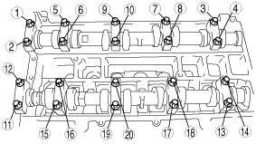
Camshaft Removal Note
1. Loosen the camshaft cap bolts in 2—3 steps in the order shown in the figure.
am6zzw00007645
|
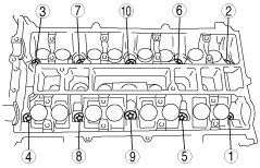
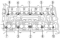
Cylinder Head Removal Note
1. Loosen the cylinder head bolts in 2—3 steps in the order shown in the figure.
am6zzw00007646
|
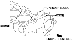
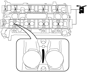
Cylinder Head Gasket Installation Note
1. Apply silicone sealant to the areas shown in the figure.
acxaaw00001646
|
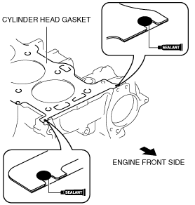
2. Install the cylinder block with a new cylinder head gasket.
3. Apply silicone sealant to the areas shown in the figure.
acxaaw00001647
|
4. Install the cylinder head referring to the Cylinder Head Installation Note.
Cylinder Head Installation Note
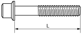
1. Measure the length of each cylinder head bolt.
am6zzw00007647
|
2. Tighten the cylinder head bolts in the order shown in the following 5 steps using the SST (49 D032 316).
am6zzw00007648
|
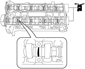
Camshaft Installation Note
1. Apply the gear oil (SAE No.90 or equivalent) to each journal of the cylinder head as shown in the figure.
aatjjw00010413
|
2. Set the cam position of No.1 cylinder at the top dead center (TDC) and install the camshaft.
3. Apply the gear oil (SAE No.90 or equivalent) to each journal of the camshaft as shown in the figure.
aatjjw00010414
|
4. Temporarily tighten the camshaft cap bolts evenly in 2—3 steps.
5. Tighten the camshaft cap bolts in the order shown in the following two steps.
am6zzw00007649
|