TRANSAXLE FLUID TEMPERATURE (TFT) SENSOR INSPECTION [FS5A-EL]


id051721801000

Caution
•  Water or foreign objects entering the connector can cause a poor connection or corrosion. Be sure not to drop water or foreign objects on the connector when disconnecting it.

On‐Vehicle Inspection

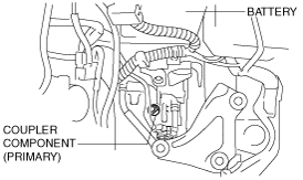
1.  Disconnect the coupler component connector.

(1)  Disconnect the negative battery cable.
(2)  Remove the air cleaner component. (See INTAKE-AIR SYSTEM REMOVAL/INSTALLATION [L8, LF, L5].)
(3)  Disconnect the coupler component connector (primary).
am6zzw00001284

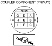
2.  Measure the resistance between terminals E and H.

•  If there is any malfunction, replace the coupler component (primary). (See TRANSAXLE FLUID TEMPERATURE (TFT) SENSOR REMOVAL/INSTALLATION [FS5A-EL].)
am6zzw00000336

Transaxle fluid temperature (TFT) sensor

ATF temperature (°C {°F})

Resistance (kilohm)

–20 {–4}
236—324
0 {32}
84.3—110
20 {68}
33.5—42.0
40 {104}
14.7—17.9
60 {140}
7.08—8.17
80 {176}
3.61—4.15
100 {212}
1.96—2.24
120 {248}
1.13—1.28
130 {266}
0.87—0.98


Off‐Vehicle Inspection

Warning
•  A hot transaxle and ATF can cause severe burns. Turn off the engine and wait until they are cool.

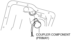
1.  Remove the coupler component (primary).

(1)  Disconnect the negative battery cable.
(2)  Remove the air cleaner component. (See INTAKE-AIR SYSTEM REMOVAL/INSTALLATION [L8, LF, L5].)
(3)  Clean the transaxle exterior throughout with a steam cleaner or cleaning solvents.
(4)  Remove the aerodynamic under cover NO.2. (See AERODYNAMIC UNDER COVER NO.2 REMOVAL/INSTALLATION.)
(5)  Drain the ATF into a separate suitable container.
(6)  Remove the front crossmember. (See FRONT CROSSMEMBER REMOVAL/INSTALLATION.)
(7)  Remove the oil pan. (See PRIMARY CONTROL VALVE BODY REMOVAL [FS5A-EL].)
(8)  Remove the control valve body. (See PRIMARY CONTROL VALVE BODY REMOVAL [FS5A-EL].)
(9)  Disconnect the coupler component connector (primary).
am6zzw00001284
(10)  Remove the coupler component (primary) from transaxle case.
am6zzw00002725

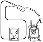
2.  Place the TFT sensor and a thermometer in ATF as shown, and heat the ATF gradually.

adejjw00001077

3.  Measure the resistance between terminals E and H.

am6zzw00000336

•  If there is any malfunction, replace the coupler component (primary). (SeeTRANSAXLE FLUID TEMPERATURE (TFT) SENSOR REMOVAL/INSTALLATION [FS5A-EL].)

Transaxle fluid temperature (TFT) sensor

ATF temperature (°C {°F})

Resistance (kilohm)

-20 {-4}
236—324
0 {32}
84.3—110
20 {68}
33.5—42.0
40 {104}
14.7—17.9
60 {140}
7.08—8.17
80 {176}
3.61—4.15
100 {212}
1.96—2.24
120 {248}
1.13—1.28
130 {266}
0.87—0.98