TRANSAXLE FLUID TEMPERATURE (TFT) SENSOR REMOVAL/INSTALLATION [FS5A-EL]
id051721801100
-
Warning
-
• When the transaxle and ATF are hot, they can badly burn. Turn off the engine and wait until they are cool before replacing the ATF.
1. Remove the control valve body.
- (1) Disconnect the negative battery cable.
- (2) Clean the transaxle exterior throughout with a steam cleaner or cleaning solvents.
- (3) Remove the aerodynamic under cover NO.2. (SeeAERODYNAMIC UNDER COVER NO.2 REMOVAL/INSTALLATION.)
- (4) Drain the ATF into a separate suitable container. (See AUTOMATIC TRANSAXLE FLUID (ATF) REPLACEMENT [FS5A-EL].)
- (5) Remove the front crossmember. (See FRONT CROSSMEMBER REMOVAL/INSTALLATION.)
- (6) Remove the oil pan. (See PRIMARY CONTROL VALVE BODY REMOVAL [FS5A-EL].)
- (7) Remove the control valve body. (See PRIMARY CONTROL VALVE BODY REMOVAL [FS5A-EL].)
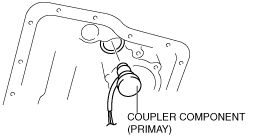
- (8) Remove the coupler component (primary) from transaxle case.
-
- (9) Remove the O-ring from the coupler component (primary).
2. Install the control valve body.
- (1) Apply ATF to a new O-ring and install it on the coupler component (primary).
- (2) Install the coupler component (primary) to transaxle case.
- (3) Install the control valve body. (See PRIMARY CONTROL VALVE BODY INSTALLATION [FS5A-EL].)
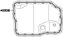
- (4) Apply a light coat of silicon sealant (TB1217E) to the contact surfaces of the oil pan and transaxle case.
3. Install the oil pan.
-
Tightening torque
-
8—11 N·m {82—112 kgf·cm, 71—97 in·lbf}
4. Install the front crossmember. (See FRONT CROSSMEMBER REMOVAL/INSTALLATION.)
5. Add ATF. (See AUTOMATIC TRANSAXLE FLUID (ATF) REPLACEMENT [FS5A-EL].)
6. Install the aerodynamic under cover NO.2. (SeeAERODYNAMIC UNDER COVER NO.2 REMOVAL/INSTALLATION.)
7. Connect the negative battery cable.
8. Perform the mechanical system test. (See MECHANICAL SYSTEM TEST [FS5A-EL].)