 |
am6zzw00002907
SECONDARY CONTROL VALVE BODY INSTALLATION [FS5A-EL]
id051721807600
On‐Vehicle Installation
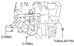
1. Install the tubular pin and new O-ring to the transaxle case.
am6zzw00002907
|
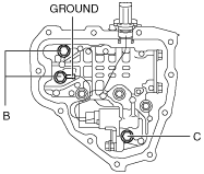
2. Install the secondary control valve body component and ground.
am6zzw00002908
|
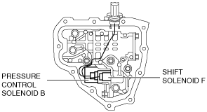
3. Match the connector colors, then connect the solenoid connector.
am6zzw00002909
|
|
Spring |
Connector color (harness side) |
|---|---|
|
Pressure control solenoid B
|
White
|
|
Shift solenoid F
|
Black
|
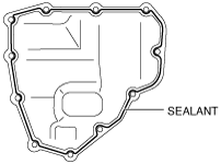
4. Apply a light coat of silicon sealant to the contact surfaces of the oil cover and transaxle case.
am6zzw00002910
|
5. Install the oil cover.
6. Add ATF. (See AUTOMATIC TRANSAXLE FLUID (ATF) REPLACEMENT [FS5A-EL].)
7. Install the aerodynamic under cover NO.2. (See AERODYNAMIC UNDER COVER NO.2 REMOVAL/INSTALLATION.)
8. Connect the EPS control module connector. (See EPS CONTROL MODULE REMOVAL/INSTALLATION.)
9. Install the battery and battery tray. (SeeBATTERY REMOVAL/INSTALLATION [L8, LF, L5].)
10. Connect the negative battery cable.
11. Carry out the mechanical system test. (See MECHANICAL SYSTEM TEST [FS5A-EL].)