am6zzw00001305
|
SOLENOID VALVE INSPECTION (SECONDARY CONTROL VALVE BODY) [FS5A-EL]
id051721807900
On-Vehicle Inspection
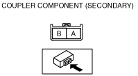
1. Disconnect the coupler component connector (secondary).
am6zzw00001305
|
2. Measure the resistance between the following terminals.
am6zzw00000421
|
|
Solenoid valve
|
Terminal
|
Resistance (ohm)
|
|
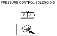
Pressure control solenoid B
|
A—GND
|
1.0—4.2
|
|
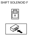
Shift solenoid F
|
B—GND
|
8.4—21.8
|
Off‐Vehicle Inspection
1. Disconnect the negative battery cable.
2. Remove the battery and battery tray. (See BATTERY REMOVAL/INSTALLATION [L8, LF, L5].)
3. Remove the solenoid valve. (SeeSOLENOID VALVE REMOVAL/INSTALLATION (SECONDARY CONTROL VALVE BODY) [FS5A-EL].)
4. Measure the resistance of each solenoid valve individually.
Pressure control solenoid B
am6zzw00000422
|
Shift solenoid F
am6zzw00000423
|
Operating Inspection
1. Disconnect the coupler component connector (secondary).
am6zzw00001305
|
2. Apply battery positive voltage to terminals A and B and battery negative voltage to GND, and verify that operating sound is heard from solenoid.
am6zzw00000421
|