 |
am6zzw00002665
DTC B00D5:11/B00D5:12
id080200826800
System Malfunction Location
|
DTC |
System Malfunction Location |
|---|---|
|
M-MDS display |
|
|
B00D5:11
|
PAD indicator light circuit short to body ground
|
|
B00D5:12
|
PAD indicator light circuit short to power supply
|
Detection Condition
Possible Causes
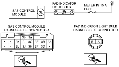
System Wiring Diagram
am6zzw00002665
|
Diagnostic Procedure
|
STEP |
INSPECTION |
ACTION |
|
|---|---|---|---|
|
1
|
INSPECT BATTERY
• Measure the battery positive voltage.
• Is the voltage 8 V―16 V?
|
Yes
|
Go to the next step.
|
|
No
|
Battery is malfunctioning
Inspect the charge/discharge system.
|
||
|
2
|
INSPECT FUSE
• Switch the ignition to off.
• Disconnect the negative battery cable and wait for 1 min or more.
• Remove the METER IG 15 A fuse.
• Is the fuse normal?
|
Yes
|
Install the fuse, then go to the next step.
|
|
No
|
Replace the fuse.
|
||
|
3
|
INSPECT PAD INDICATOR LIGHT BULB CONNECTOR
• Remove the center panel lower.
• Remove the PAD indicator light bulb.
• Inspect the PAD indicator light bulb connector. (Corrosion, damage, and disconnected pins)
• Is there any malfunction of the PAD indicator light bulb connector?
|
Yes
|
Go to the next step.
|
|
No
|
Repair the PAD indicator light bulb wiring harness.
|
||
|
4
|
INSPECT PAD INDICATOR LIGHT BULB
• Verify the PAD indicator light bulb capacity (W).
• Has a PAD indicator light bulb with a bulb capacity (W) that is the same as a standard product been installed?
|
Yes
|
Go to the next step.
|
|
No
|
Replace the bulb with a standard capacity (W) PAD indicator light bulb.
After replacement, go to Step 9.
|
||
|
5
|
INSPECT WIRING HARNESS BETWEEN BATTERY AND PAD INDICATOR LIGHT BULB
• Connect the negative battery cable.
• Switch the ignition to ON.
• Measure the PAD indicator light bulb connector terminal A voltage.
• Is the voltage 8 V or more?
|
Yes
|
Go to the next step.
|
|
No
|
Repair the wiring harness between the battery and PAD indicator light bulb.
|
||
|
6
|
INSPECT PAD INDICATOR
• Ground PAD indicator connector terminal B using a jumper wire.
• Switch the ignition to ON.
• Does the PAD indicator illuminate?
|
Yes
|
Go to the next step.
|
|
No
|
Replace the PAD indicator light bulb.
|
||
|
7
|
INSPECT WIRING HARNESS BETWEEN PAD INDICATOR LIGHT BULB AND SAS CONTROL MODULE
• Switch the ignition to off.
• Disconnect the negative battery cable and wait for 1 min or more.
• Remove the column cover.
• Remove the clock spring.
• Remove the glove compartment.
• Disconnect the passenger-side air bag module connector.
• Disconnect the driver and passenger-side side air bag module connectors.
• Remove the C-pillar trim. (4SD)
• Remove the headliner. (5HB, WGN)
• Disconnect the driver and passenger-side curtain air bag module connectors.
• Remove the B-pillar lower trim. (4SD)
• Disconnect the driver and passenger-side pre-tensioner seat belt connectors.
• Remove the rear console.
• Disconnect the SAS control module connectors.
• Inspect the wiring harness between PAD indicator light bulb connector terminal B and SAS control module connector terminal 3L for the following:
• Is the wiring harness normal?
|
Yes
|
Go to the next step.
|
|
No
|
Repair the wiring harness between the PAD indicator light bulb and SAS control module.
|
||
|
8
|
INSPECT THE WIRING HARNESS BETWEEN SAS CONTROL MODULE AND PAD INDICATOR LIGHT BULB FOR A SHORT CIRCUIT TO THE POWER SUPPLY
• Connect the negative battery cable.
• Switch the ignition to ON.
• Measure the voltage of SAS control module connector terminal 3L.
• Is the voltage measured?
|
Yes
|
Repair the wiring harness between the PAD indicator light bulb and SAS control module.
|
|
No
|
Go to the next step.
|
||
|
9
|
PERFORM SAS CONTROL MODULE DTC INSPECTION
• Switch the ignition to off.
• Disconnect the negative battery cable and wait for 1min or more.
• Reconnect all disconnected connectors.
• Connect the negative battery cable.
• Switch the ignition to ON.
• Clear the DTC for the SAS control module using the M-MDS.
(See CLEARING DTC.)
• Perform the DTC inspection for the SAS control module using the M-MDS.
(See DTC DISPLAY.)
• Are the same DTCs present?
|
Yes
|
Replace the SAS control module.
|
|
No
|
DTC troubleshooting completed.
|
||