|
1
|
INSPECT EGI 5 A FUSE
• Switch the ignition to off.
• Disconnect the negative battery cable.
• Remove the EGI 5 A fuse.
• Inspect the fuse.
• Is the EGI 5 A fuse normal?
|
Yes
|
Go to the next step.
|
|
No
|
Replace the EGI 5 A fuse.
After replacement, go to Step 6.
|
|
2
|
INSPECT MAIN RELAY
• Remove the main relay.
• Is the main relay normal?
|
Yes
|
Go to the next step.
|
|
No
|
Replace the main relay.
After replacement, go to Step 6.
|
|
3
|
INSPECT BATTERY
• Measure the battery positive voltage.
• Is the voltage 9—16V?
|
Yes
|
Go to the next step.
|
|
No
|
Higher than specification
• Recharge or replace the battery, then go to Step 6.
Lower than specification
• Replace or charge the battery, then go to Step 6.
|
|
4
|
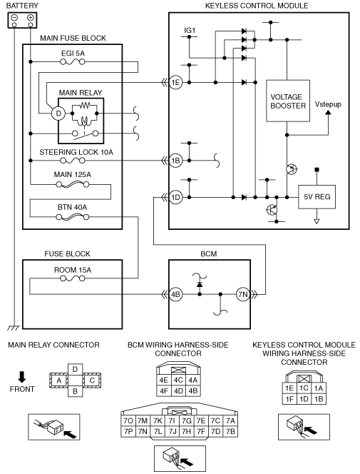
INSPECT KEYLESS CONTROL MODULE CONNECTOR CONDITION
• Disconnect the keyless control module connector.
• Inspect the connector and terminals (corrosion, damage, pin disconnection).
• Is the connector normal?
|
Yes
|
Go to the next step.
|
|
No
|
Repair/replace the connector or terminal.
After repair procedure, go to Step 6.
|
|
5
|
INSPECT WIRING HARNESS BETWEEN BATTERY AND KEYLESS CONTROL MODULE
• Inspect wiring harness between battery and keyless control module connector terminal 1E for the following:
-
― Short to ground
― Open circuit
• Is the wiring harness normal?
|
Yes
|
Go to the next step.
|
|
No
|
Repair/replace the wiring harness.
After repair procedure, go to the next step.
|
|
6
|
VERIFY DTC
• Install the EGI 5 A fuse and main relay.
• Reconnect the disconnected connectors and the negative battery cable.
• Clear DTC using the M-MDS.
• Verify DTC using the M-MDS.
• Is the same DTC present?
|
Yes
|
Repeat the inspection from Step 1.
If the malfunction recurs, replace the keyless control module.
Go to the next step.
|
|
No
|
Go to the next step.
|
|
7
|
VERIFY THAT NO OTHER DTCs ARE PRESENT
• Are there other DTCs output?
|
Yes
|
Perform the corresponding DTC inspection.
|
|
No
|
DTC troubleshooting completed.
|