|
1
|
INSPECT COMBINED SENSOR CONNECTOR CONDITION
• Switch the ignition to off.
• Disconnect the negative battery cable.
• Disconnect the combined sensor connector.
• Inspect the connector and terminals (corrosion, damage, pin disconnection).
• Is the connector normal?
|
Yes
|
Go to the next step.
|
|
No
|
Repair/replace the connector or terminal.
After repair procedure, go to Step 9.
|
|
2
|
INSPECT COMBINED SENSOR
• Inspect the combined sensor.
• Is the combined sensor normal?
|
Yes
|
Go to the next step.
|
|
No
|
Replace the combined sensor.
(See COMBINED SENSOR REMOVAL/INSTALLATION.)After replacement, go to Step 9. |
|
3
|
INSPECT DSC HU/CM CONNECTOR CONDITION
• Disconnect the DSC HU/CM connector.
• Inspect the connector and terminals (corrosion, damage, pin disconnection).
• Is the connector normal?
|
Yes
|
Go to the next step.
|
|
No
|
Repair/replace the connector or terminal.After repair procedure, go to Step 9.
|
|
4
|
INSPECT BCM CONNECTOR CONDITION
• Disconnect the BCM connector.
• Inspect the connector and terminals (corrosion, damage, pin disconnection).
• Is the connector normal?
|
Yes
|
Go to the next step.
|
|
No
|
Repair/replace the connector or terminal.
After repair procedure, go to Step 9.
|
|
5
|
INSPECT KEYLESS CONTROL MODULE CONNECTOR CONDITION
• Disconnect the keyless control module connector
• Inspect the connector and terminals (corrosion, damage, pin disconnection).
• Is the connector normal?
|
Yes
|
Go to the next step.
|
|
No
|
Repair/replace the connector or terminal.
After repair procedure, go to Step 9.
|
|
6
|
INSPECT ABS DRIVER CIRCUIT FOR SHORT CIRCUIT TO GROUND
• Inspect for continuity between the following terminals and body ground.
-
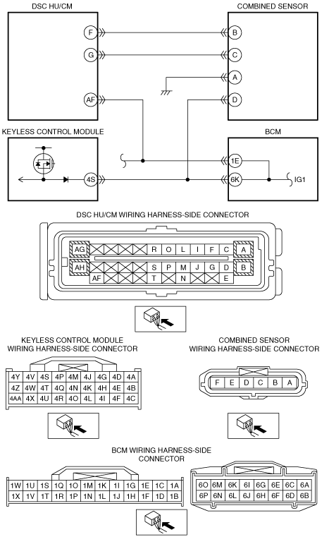
― Combined sensor connector terminal D
― DSC HU/CM connector terminal AF
• Is there continuity?
|
Yes
|
Repair/replace the malfunctioning vehicle wiring harness.After repair procedure, go to Step 9.
|
|
No
|
Go to the next step.
|
|
7
|
INSPECT DSC HU/CM
• Reconnect the DSC HU/CM connector.
• Reconnect the negative battery cable.
• Switch the ignition to ON.
• Measure the voltage at DSC HU/CM connector terminal AF.
• Is the voltage normal?
|
Yes
|
Go to the next step.
|
|
No
|
Replace the DSC HU/CM.
After replacement, go to Step 9.
|
|
8
|
INSPECT BCM
• Switch the ignition to off.
• Disconnect the negative battery cable.
• Reconnect the BCM connector.
• Reconnect the negative battery cable.
• Switch the ignition to ON.
• Measure the voltage at BCM connector terminal 1E and 6K.
• Is the voltage normal?
|
Yes
|
Go to the next step.
|
|
No
|
Replace the BCM.
After replacement, go to the next step.
|
|
9
|
VERIFY DTC
• Reconnect the disconnected connectors and the negative battery cable.
• Clear DTC using the M-MDS.
• Verify DTC using the M-MDS.
• Is the same DTC present?
|
Yes
|
Repeat the inspection from Step 1.
If the malfunction recurs, replace the keyless control module.
|
|
No
|
Go to the next step.
|
|
10
|
VERIFY THAT NO OTHER DTCs ARE PRESENT
• Are there other DTCs output?
|
Yes
|
Perform the corresponding DTC inspection.
|
|
No
|
DTC troubleshooting completed.
|