|
1
|
INSPECT RELAY
• Switch the ignition to off.
• Disconnect the negative battery cable.
• Remove the starter relay.
• Inspect the starter relay.
• Is there any malfunction?
|
Yes
|
Replace the starter relay, then go to Step 8.
|
|
No
|
Go to the next step.
|
|
2
|
INSPECT KEYLESS CONTROL MODULE CONNECTOR CONDITION
• Disconnect the keyless control module connector.
• Inspect the connector and terminals (corrosion, damage, pin disconnection).
• Is there any malfunction?
|
Yes
|
Repair or replace the connector or terminals, then go to Step 8.
|
|
No
|
Go to the next step.
|
|
3
|
INSPECT STARTER RELAY CIRCUIT FOR SHORT TO GROUND
• Inspect for continuity between the following terminals and body ground:
-
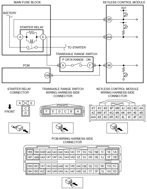
― Starter relay terminal E (wiring harness-side)
― Starter relay terminal A (wiring harness-side)
• Is there continuity?
|
Yes
|
Repair or replace the wiring harness for a possible short to ground, then go to Step 8.
|
|
No
|
Go to the next step.
|
|
4
|
INSPECT PCM CONNECTOR CONDITION
• Disconnect the PCM connector.
• Inspect the connector and terminals (corrosion, damage, pin disconnection).
• Is there any malfunction?
|
Yes
|
Repair or replace the connector or terminals, then go to Step 8.
|
|
No
|
Go to the next step.
|
|
5
|
INSPECT STARTER RELAY CIRCUIT FOR SHORT TO GROUND
• Inspect for continuity between transaxle range switch terminal F (wiring harness-side) and body ground.
• Is there continuity?
|
Yes
|
Repair or replace the wiring harness for a possible short to ground, then go to Step 8.
|
|
No
|
Go to the next step.
|
|
6
|
INSPECT PCM
• Reconnect the disconnected connectors.
• Reconnect the negative battery cable.
• Switch the ignition to ON.
• Measure the voltage between PCM terminal 1BB (wiring harness-side) and body ground.
|
Yes
|
Go to the next step.
|
|
No
|
Replace the PCM, then go to Step 8.
|
|
7
|
INSPECT KEYLESS CONTROL MODULE
• Switch the ignition to off.
• Disconnect the negative battery cable.
• Disconnect the PCM connector.
• Reconnect the negative battery cable.
• Measure the voltage between keyless control module terminal 4AA (wiring harness-side) and body ground with the shift lever in P or N range.
• Is the voltage more than 4 V?
|
Yes
|
Go to the next step.
|
|
No
|
Replace the keyless control module, then go to the next step.
|
|
8
|
VERIFY TROUBLESHOOTING COMPLETED
• Make sure to reconnect the disconnected connectors.
• Reconnect the negative battery cable.
• Clear the DTC from keyless control module memory using the M-MDS.
• Perform the advanced keyless entry and push button start system DTC inspection using the M-MDS.
• Is the same DTC present?
|
Yes
|
Repeat the inspection from Step 1.
If the malfunction recurs, replace the keyless control module, then go to the next step.
|
|
No
|
Go to the next step.
|
|
9
|
VERIFY THAT NO OTHER DTCs ARE PRESENT
• Are any DTCs present?
|
Yes
|
Go to the applicable DTC inspection.
|
|
No
|
DTC troubleshooting completed.
|