THEFT-DETERRENT SIREN AND TILT SENSOR REMOVAL/INSTALLATION
id091400822500
-
Note
-
• The tilt sensor are built into the theft-deterrent siren.
-
Caution
-
• The clearance between the angle sensor and bracket is set at the initial position. If the angle sensor is removed from the bracket or servicing is performed which changes the initial position, the angle sensor will not operate correctly.
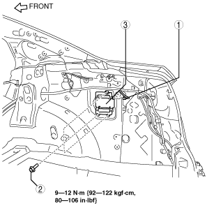
4SD
1. Disconnect the negative battery cable.
2. Remove the following parts:
- (1) Trunk end trim (See TRUNK END TRIM REMOVAL/INSTALLATION.)
- (2) Trunk side trim (RH) (See TRUNK SIDE TRIM REMOVAL/INSTALLATION.)
3. Remove in the order indicated in the table.
|
1
|
Connector
|
|
2
|
Bolt
|
|
3
|
Theft-deterrent siren
|
4. Install in the reverse order of removal.
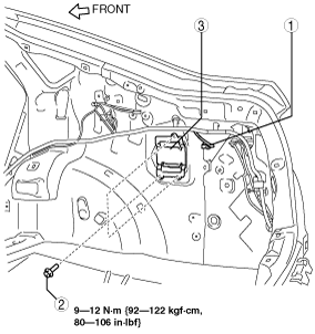
5HB
1. Disconnect the negative battery cable.
2. Remove the following parts:
- (1) Trunk end trim (See TRUNK END TRIM REMOVAL/INSTALLATION.)
- (2) Rear scuff plate (RH) (See REAR SCUFF PLATE REMOVAL/INSTALLATION.)
- (3) Tire house trim (RH) (See TIRE HOUSE TRIM REMOVAL/INSTALLATION.)
- (4) Trunk side upper trim (RH) (See TRUNK SIDE UPPER TRIM REMOVAL/INSTALLATION.)
- (5) Trunk side trim (RH) (See TRUNK SIDE TRIM REMOVAL/INSTALLATION.)
3. Remove in the order indicated in the table.
|
1
|
Connector
|
|
2
|
Bolt
|
|
3
|
Theft-deterrent siren
|
4. Install in the reverse order of removal.
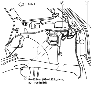
WGN
1. Disconnect the negative battery cable.
2. Remove the following parts:
- (1) Trunk end trim (See TRUNK END TRIM REMOVAL/INSTALLATION.)
- (2) Rear scuff plate (RH) (See REAR SCUFF PLATE REMOVAL/INSTALLATION.)
- (3) Tire house trim (RH) (See TIRE HOUSE TRIM REMOVAL/INSTALLATION.)
- (4) Trunk side upper trim (RH) (See TRUNK SIDE UPPER TRIM REMOVAL/INSTALLATION.)
- (5) Trunk side trim (RH) (See TRUNK SIDE TRIM REMOVAL/INSTALLATION.)
3. Remove in the order indicated in the table.
|
1
|
Connector
|
|
2
|
Bolt
|
|
3
|
Theft-deterrent siren
|
4. Install in the reverse order of removal.