 |
am6zzw00004226
REAR VEHICLE MONITORING CONTROL MODULE INSPECTION
id092200146100
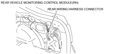
Rear vehicle monitoring control module (RH)
1. Remove the trunk end trim. (See TRUNK END TRIM REMOVAL/INSTALLATION.)
2. Remove the rear scuff plate. (See REAR SCUFF PLATE REMOVAL/INSTALLATION.) (5HB, Wagon)
3. Remove the tire house trim. (See TIRE HOUSE TRIM REMOVAL/INSTALLATION.) (5HB, Wagon)
4. Remove the trunk side upper trim. (See TRUNK SIDE UPPER TRIM REMOVAL/INSTALLATION.) (5HB, Wagon)
5. Remove the trunk side trim. (See TRUNK SIDE TRIM REMOVAL/INSTALLATION.)
6. Measure the rear vehicle monitoring control module terminal voltage using the rear wiring harness connector in the position shown in the figure.
am6zzw00004226
|
Terminal Voltage Table (Reference)
Rear vehicle monitoring control module (RH)
am6zzw00004227
|
|
Terminal |
Signal |
Connected to |
Measurement condition |
Voltage (V)/Continuity |
Inspection item(s) |
|
|---|---|---|---|---|---|---|
|
A
|
—
|
—
|
—
|
—
|
—
|
|
|
B
|
—
|
—
|
—
|
—
|
—
|
|
|
C
|
—
|
—
|
—
|
—
|
—
|
|
|
D
|
RVM switch signal
|
RVM switch
|
Switch the ignition to ON
|
RVM switch pressed
|
1.0 or less
|
• RVM switch
• Related wiring harness
|
|
RVM switch not pressed
|
+B
|
|||||
|
E
|
—
|
—
|
—
|
—
|
—
|
|
|
F
|
Power supply
|
Fuse
|
Switch the ignition to ON
|
+B
|
• Fuse
• Related wiring harness
|
|
|
Switch the ignition to off
|
1.0 or less
|
|||||
|
G
|
—
|
—
|
—
|
—
|
—
|
|
|
H
|
Ground
|
Body ground
|
Under any condition
|
1.0 or less
|
• Related wiring harness
|
|
|
I
|
—
|
—
|
—
|
—
|
—
|
|
|
J
|
CAN2_H
|
Rear vehicle monitoring control module (LH)
|
Terminal used for communication therefore determination based on terminal voltage is not possible.
|
|||
|
K
|
—
|
—
|
—
|
—
|
—
|
|
|
L
|
CAN2_L
|
Rear vehicle monitoring control module (LH)
|
Terminal used for communication therefore determination based on terminal voltage is not possible.
|
|||
|
M
|
CAN_H
|
—
|
Terminal used for communication therefore determination based on terminal voltage is not possible.
|
|||
|
N
|
—
|
—
|
—
|
—
|
—
|
|
|
O
|
CAN_L
|
—
|
Terminal used for communication therefore determination based on terminal voltage is not possible.
|
|||
|
P
|
CAN_L
|
—
|
Terminal used for communication therefore determination based on terminal voltage is not possible.
|
|||
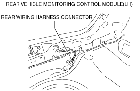
Rear vehicle monitoring control module (LH)
1. Remove the trunk mat.
2. Remove the trunk board. (4SD, Wagon)
3. Remove the trunk end trim. (See TRUNK END TRIM REMOVAL/INSTALLATION.)
4. Measure the rear vehicle monitoring control module terminal voltage using the rear wiring harness connector in the position shown in the figure.
am6zzw00004228
|
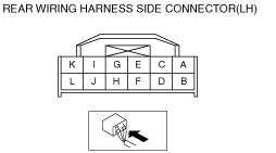
Rear vehicle monitoring control module (LH)
am6zzw00004229
|
|
Terminal |
Signal |
Connected to |
Measurement condition |
Voltage (V)/Continuity |
Inspection item(s) |
|
|---|---|---|---|---|---|---|
|
A
|
RVM warning indicator light signal (LH)
|
RVM warning indicator light (LH)
|
Switch the ignition to ON
|
LED off
|
1.0 or less
|
• RVM warning indicator light (LH)
• Related wiring harness
|
|
LED on
|
3.0—5.0
|
|||||
|
B
|
RVM warning indicator light ground signal (LH)
|
RVM warning indicator light (LH)
|
Under any condition
|
1.0 or less
|
• RVM warning indicator light LED (LH)
• Related wiring harness
|
|
|
C
|
RVM warning indicator light signal (RH)
|
RVM warning indicator light (RH)
|
Switch the ignition to ON
|
LED off
|
1.0 or less
|
• RVM warning indicator light LED (RH)
• Related wiring harness
|
|
LED on
|
3.0—5.0
|
|||||
|
D
|
RVM warning indicator light ground signal (RH)
|
RVM warning indicator light (RH)
|
Under any condition
|
1.0 or less
|
• RVM warning indicator light LED (RH)
• Related wiring harness
|
|
|
E
|
—
|
—
|
—
|
—
|
—
|
|
|
F
|
CAN_L
|
—
|
Terminal used for communication therefore determination based on terminal voltage is not possible.
|
|||
|
G
|
Power supply
|
Fuse
|
Switch the ignition to ON
|
+B
|
• Fuse
• Related wiring harness
|
|
|
Switch the ignition to off
|
1.0 or less
|
|||||
|
H
|
Ground
|
Body ground
|
Under any condition
|
1.0 or less
|
• Related wiring harness
|
|
|
I
|
—
|
—
|
—
|
—
|
—
|
|
|
J
|
CAN2_H
|
Rear vehicle monitoring control module (RH)
|
Terminal used for communication therefore determination based on terminal voltage is not possible.
|
|||
|
K
|
—
|
—
|
—
|
—
|
—
|
|
|
L
|
CAN2_L
|
Rear vehicle monitoring control module (RH)
|
Terminal used for communication therefore determination based on terminal voltage is not possible.
|
|||