|
1
|
VERIFY FREEZE FRAME DATA HAS BEEN RECORDED
• Has the FREEZE FRAME DATA been recorded?
|
Yes
|
Go to the next step.
|
|
No
|
Record the FREEZE FRAME DATA on the repair order, then go to the next step.
|
|
2
|
VERIFY RELATED SERVICE INFORMATION AVAILABILITY
• Verify related Service Information availability.
• Is any related Service Information available?
|
Yes
|
Perform repair or diagnosis according to the available Service Information.
• If the vehicle is not repaired, go to the next step.
|
|
No
|
Go to the next step.
|
|
3
|
VERIFY CURRENT INPUT SIGNAL STATUS: IS CONCERN INTERMITTENT OR CONSTANT
• Turn the ignition switch to the LOCK position.
• Start engine.
• Access TSS PID using the M-MDS.
-
― IG ON: 0 rpm
― Idle: Within 600—700 rpm
• Are PID readings within specification?
|
Yes
|
Go to the intermittent concern troubleshooting procedure, then go to Step 10.
|
|
No
|
Go to the next step.
|
|
4
|
INSPECT INPUT/TURBINE SPEED SENSOR CONNECTOR FOR POOR CONNECTION
• Turn the ignition switch to the LOCK position.
• Disconnect the input/turbine speed sensor connector.
• Inspect for poor connection (such as damaged/pulled-out pins, corrosion).
• Is the connection normal?
|
Yes
|
Go to the next step.
|
|
No
|
Repair or replace connector and/or terminals, then go to Step 10.
|
|
5
|
INSPECT INPUT/TURBINE SPEED SENSOR RESISTANCE
• Measure resistance between input/turbine speed sensor terminals (part-side).
• Is resistance within 253—604 ohms between input/turbine speed sensor terminals (part-side)?
|
Yes
|
Go to the next step.
|
|
No
|
Replace the input/turbine speed sensor, then go to Step 10.
|
|
6
|
INSPECT INPUT/TURBINE SPEED SENSOR
• Remove the input/turbine speed sensor.
• Is there iron powder stuck on input/turbine speed sensor?
|
Yes
|
Clean input/turbine speed sensor, then go to Step 10
|
|
No
|
Go to the next step.
|
|
7
|
INSPECT PCM CONNECTOR FOR POOR CONNECTION
• Disconnect the PCM connector.
• Inspect for poor connection (such as damaged/pulled-out pins, corrosion).
• Is the connection normal?
|
Yes
|
Go to the next step.
|
|
No
|
Repair or replace connector and/or terminals, then go to Step 10.
|
|
8
|
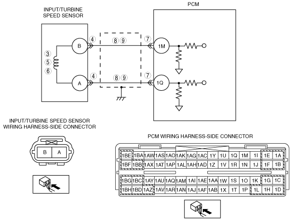
INSPECT INPUT/TURBINE SPEED SENSOR CIRCUIT FOR OPEN CIRCUIT
• Inspect input/turbine speed sensor terminals (wiring harness-side) and PCM terminals (wiring harness-side).
-
― B and 1M
― A and 1Q
• Is there continuity?
|
Yes
|
Go to the next step.
|
|
No
|
Repair or replace the wiring harness, then go to Step 10.
|
|
9
|
INSPECT INPUT/TURBINE SPEED SENSOR CIRCUIT FOR SHORT TO GROUND
• Inspect input/turbine speed sensor terminal (wiring harness-side) and body ground.
-
― A and body ground
― B and body ground
• Is there continuity?
|
Yes
|
Repair or replace the wiring harness, then go to the next step.
|
|
No
|
Go to the next step.
|
|
10
|
VERIFY TROUBLESHOOTING OF DTC P0715 COMPLETED
• Make sure to reconnect all the disconnected connectors.
• Clear the DTC from memory using the M-MDS.
• Drive the vehicle with vehicle speed 41 km/h {25 mph} or more for 0.8 s or more.
• Are any DTCs present?
|
Yes
|
Replace the PCM, then go to the next step.
|
|
No
|
Go to the next step.
|
|
11
|
VERIFY AFTER REPAIR PROCEDURE
• Perform the “After Repair Procedure”.
• Are any DTCs present?
|
Yes
|
Go to the applicable DTC inspection.
|
|
No
|
DTC troubleshooting completed.
|