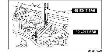
1. Install the SST.
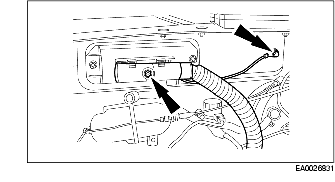
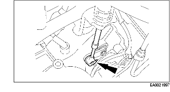
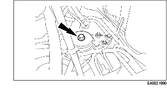
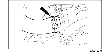
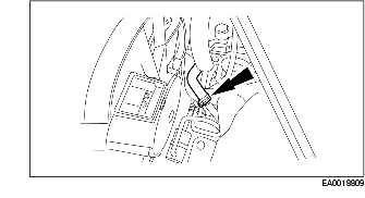
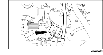
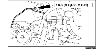
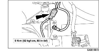
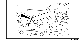
2. Disconnect the ground strap.
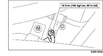
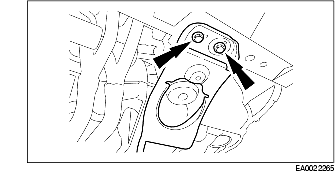
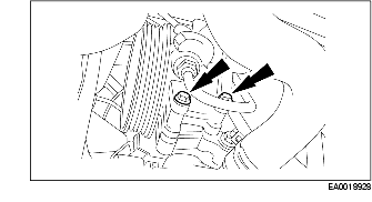
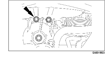
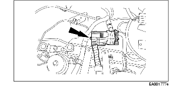
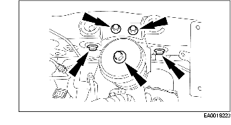
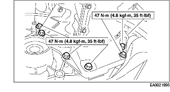
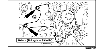
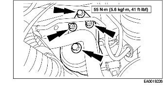
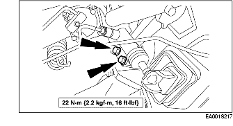
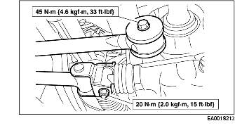
3. Remove the engine mount upper bracket.
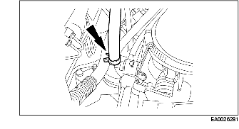
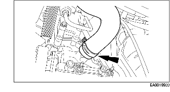
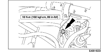
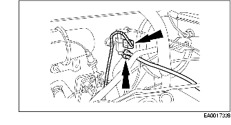
4. Disconnect the ground wire.
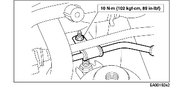
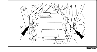
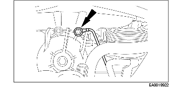
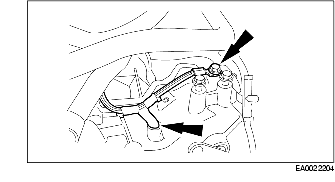
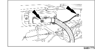
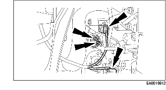
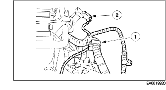
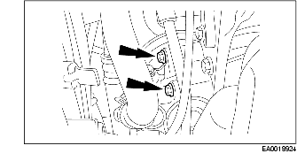
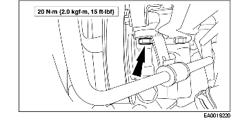
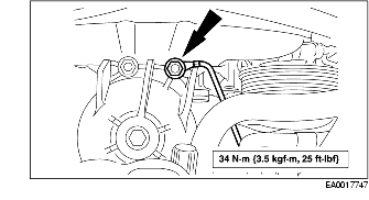
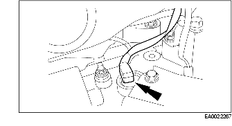
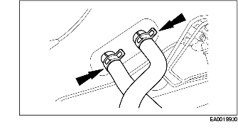
5. Disconnect the power steering line bracket.
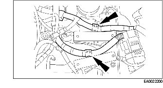
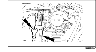
6. Disconnect the power steering line bracket and position the line aside.
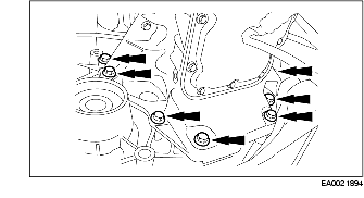
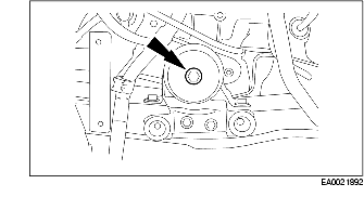
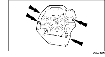
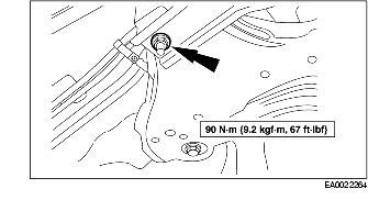
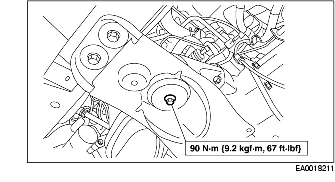
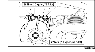
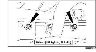
7. Remove the engine mount.
8. To install, reverse the removal procedure.
1. Relieve the fuel system pressure.
2. Remove the battery tray. (See BATTERY REMOVAL/INSTALLATION [YF (2.0L Zetec)].)
3. Remove the air cleaner assembly. (See AIR CLEANER REMOVAL/INSTALLATION [YF (2.0L Zetec)].)
4. Drain the engine coolant. (See ENGINE COOLANT REPLACEMENT [YF (2.0L Zetec)].)
5. Recover the A/C system refrigerant. (See DISCHARGING AND RECOVERY.)
6. Disconnect the fuel line. (See QUICK RELEASE CONNECTOR REMOVAL/INSTALLATION [YF (2.0L Zetec)].)
7. Disconnect the throttle cable and speed control cable (if equipped).
8. Disconnect the exhaust gas recirculation (EGR) vacuum regulator valve.
9. Disconnect the brake booster vacuum supply hose.
10. Disconnect the powertrain control module (PCM) wire harness and ground.
11. Disconnect the ground wire.
12. Disconnect the wire harness connector.
13. Disconnect the power distribution box electrical connectors.
14. Disconnect wire harness connectors from the battery tray brackets.
15. Disconnect the vacuum lines at the evaporative emission (EVAP) canister.
16. Remove the bolt and the throttle cable bracket and position the cable aside.
17. Disconnect the upper radiator hose.
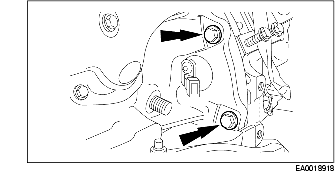
18. Remove the power steering line bracket bolt.
19. Remove the power steering line bracket bolt.
20. Remove the upper power steering pump bolts.
21. Disconnect the coolant hose.
22. Disconnect the heater hoses.
23. Remove the speed control unit and position aside (if equipped).
24. Remove the clip and disconnect the shifter cable.
25. Remove the bolts and position the shifter cable and bracket aside.
26. Remove the A/C compressor.
27. Disconnect the coolant hose.
28. Remove the LH halfshaft.
29. Remove the transfer case. (SeeTRANSFER CASE REMOVAL [LA4AX-EL (CD4E)].)
30. Remove the front transaxle mount through bolt.
31. Disconnect the transaxle cooler lines.
32. Remove the crossmember nut.
33. Remove the bolts and remove the crossmember.
34. Remove the access cover and the four torque convertor nuts.
35. Remove the engine to transaxle bolts.
36. Disconnect the lower radiator hose.
37. Remove the lower power steering pump bolts and position the pump aside.
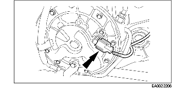
38. Remove the output shaft speed (OSS) sensor.
39. Lower the vehicle.
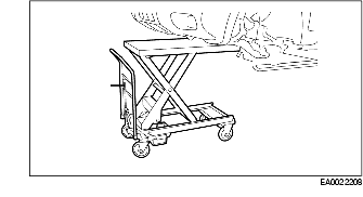
40. Secure the engine/transaxle assembly to a suitable lifting table.
41. Remove the rear transaxle mount bolt.
42. Remove the LH transaxle mount bolt.
43. Disconnect the ground cable.
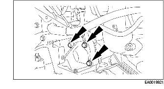
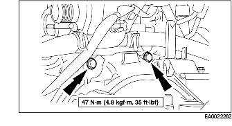
44. Remove the bolt/nuts and remove the engine mount upper bracket.
45. Lower the engine and transaxle as an assembly.
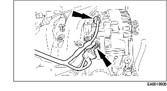
46. Disconnect the generator electrical connectors.
47. Disconnect the electrical connectors.
48. Disconnect the transaxle range (TR) sensor electrical connector.
49. Disconnect the wire harness.
50. Disconnect the ground cable.
51. Disconnect the turbine shaft speed (TSS) sensor electrical connector.
52. Remove the wire harness.
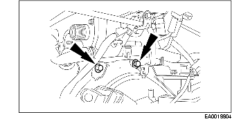
53. Remove the bolts and remove the starter.
54. Remove the engine to transaxle bolts.
55. Remove the engine to transaxle bolts and remove the transaxle.
56. Remove the flexplate.
57. Remove the rear cover plate and dowels.
58. Mount the engine on a suitable engine stand.
1. Remove the hood.
2. Relieve the fuel system pressure.
3. Remove the battery tray. (See BATTERY REMOVAL/INSTALLATION [YF (2.0L Zetec)].)
4. Remove the air cleaner assembly. (See AIR CLEANER REMOVAL/INSTALLATION [YF (2.0L Zetec)].)
5. Drain the engine coolant. (See ENGINE COOLANT REPLACEMENT [YF (2.0L Zetec)].)
6. Recover the A/C system refrigerant. (See DISCHARGING AND RECOVERY.)
7. Disconnect the fuel line. (See QUICK RELEASE CONNECTOR REMOVAL/INSTALLATION [YF (2.0L Zetec)].)
8. Disconnect the throttle cables and the speed control cable (if equipped).
9. Disconnect the exhaust gas recirculation (EGR) vacuum regulator valve.
10. Disconnect the brake booster vacuum supply hose.
11. Disconnect the powertrain control module (PCM) wire harness and ground.
12. Disconnect the ground wire.
13. Disconnect the wire harness connector.
14. Disconnect the power distribution box electrical connectors.
15. Disconnect the vacuum lines at the evaporative emission (EVAP) canister.
16. Disconnect the upper radiator hose.
17. Remove the power steering line bracket bolt.
18. Remove the power steering line bracket bolt.
19. Remove the upper power steering pump bolts.
20. Disconnect the coolant hose.
21. Disconnect the heater hoses.
22. Remove the speed control unit (if equipped) and position aside.
23. Remove the catalytic converter. (See CATALYTIC CONVERTER REMOVAL/INSTALLATION [YF (2.0L Zetec)].)
24. Disconnect the coolant hose.
25. Remove the A/C compressor.
26. Remove the halfshafts.
27. Disconnect the shifter linkages.
28. Disconnect the block heater electrical connector.
29. Remove the front transaxle mount through bolt.
30. Remove the engine to transaxle bolts.
31. Disconnect the lower radiator hose.
32. Remove the lower power steering pump bolts and position the pump aside.
33. Lower the vehicle.
34. Disconnect the power steering line brackets and position the lines out of the way.
35. Remove the clutch slave cylinder bolts.
36. Remove the clutch slave cylinder line from the bracket and position the clutch slave cylinder aside.
37. Support the engine using a suitable lifting device.
38. Remove the rear transaxle mount.
39. Remove the LH transaxle mount.
40. Disconnect the ground cable.
41. Remove the engine mount upper bracket.
42. Install the SSTand suitable lifting device and remove the engine and transaxle as an assembly.
43. Disconnect the generator electrical connectors.
44. Disconnect the electrical connectors.
45. Disconnect the vehicle speed sensor (VSS) electrical connector.
46. Disconnect the park neutral position (PNP) switch electrical connector and ground wire.
47. Disconnect the fuel charging wiring harness electrical connector.
48. Disconnect the PCM wire harness from the bracket.
49. Disconnect the ground wire.
50. Disconnect the reversing lamp switch electrical connector.
51. Remove the wire harness.
52. Remove the starter.
53. Remove the engine to transaxle bolts.
54. Remove the engine to transaxle bolts and remove the transaxle.
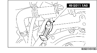
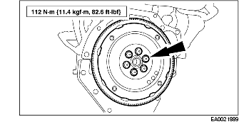
55. Using the SST, lock the flywheel to the engine.
56. Remove the bolts, clutch pressure plate and clutch disc.
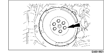
57. Remove the flywheel.
58. Remove rear cover plates and dowels.
59. Mount the engine on a suitable engine stand.
1. Remove the engine from the engine stand and secure the engine to a suitable lifting table.
2. Install the rear cover plate and dowels.
3. Install the flexplate
4. Install the transaxle onto the engine and install the bolts.
5. Install the engine to transaxle bolts.
6. Install the starter and the bolts.
7. Install the wire harness.
8. Connect the turbine shaft speed (TSS) sensor electrical connector.
9. Connect the ground cable.
10. Connect the wire harness.
11. Connect the transmission range (TR) sensor electrical connector.
12. Connect the electrical connectors.
13. Connect the generator electrical connectors.
14. Raise and support the vehicle.
15. Raise the engine and transaxle as an assembly into the vehicle.
16. Install the engine mount upper bracket.
17. Connect the ground wire.
18. Install the LH transaxle mount bolt.
19. Install the rear transaxle mount bolt.
20. Remove the lifting table.
21. Lower the vehicle.
22. Position the power steering pump and loosely install the upper bolts.
23. Raise the vehicle.
24. Install the output shaft speed (OSS) sensor.
25. Install the lower power steering bolts.
26. Connect the lower radiator hose.
27. Install the engine to transaxle bolts.
28. Install the four torque convertor nuts and the access cover.
29. Install the crossmember and install the bolts.
30. Install the crossmember nut.
31. Connect the transaxle cooler lines.
32. Install the front transaxle mount through bolt.
33. Install the transfer case. (See TRANSFER CASE REMOVAL [LA4AX-EL (CD4E)]
34. Install the LH halfshaft.
35. Install the A/C compressor.
36. Connect the coolant hose.
37. Lower the vehicle.
38. Install the shifter cable bracket.
39. Connect the shifter cable and install the retaining clip.
40. Install the speed control unit (if equipped).
41. Connect the heater hoses.
42. Connect the coolant hose.
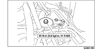
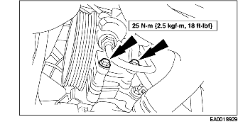
43. Tighten the upper power steering pump bolts to specification.
44. Install the power steering line bracket bolt.
45. Install the power steering line bracket bolt.
46. Connect the upper radiator hose.
47. Install the throttle cable bracket.
48. Connect the vacuum lines at the evaporative emission (EVAP) canister.
49. Connect the wire harness connectors to the battery tray brackets.
50. Connect the power distribution box electrical connections.Connect the power distribution box electrical connections.
51. Connect the wire harness electrical connector.
52. Connect the ground wire.
53. Connect the powertrain control module (PCM) wire harness and ground.
54. Connect the brake booster vacuum supply hose.
55. Connect the exhaust gas recirculation (EGR) vacuum regulator valve.
56. Connect the throttle cable and speed control cable (if equipped).
57. Connect the fuel line.
58. Install the battery tray. (See BATTERY REMOVAL/INSTALLATION [YF (2.0L Zetec)].)
59. Install the air cleaner assembly. (See AIR CLEANER REMOVAL/INSTALLATION [YF (2.0L Zetec)].)
60. Fill the engine oil.
61. Fill and bleed the engine cooling system. (See ENGINE COOLANT REPLACEMENT [YF (2.0L Zetec)].)
62. Charge the A/C system.
1. Support the engine with a suitable lifting device and remove the engine from the engine stand.
2. Install the rear cover plate and dowels.
3. Install the flywheel.
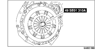
4. Using the SST, position the clutch disc onto the flywheel.
5. Position the clutch pressure plate onto the flywheel, install the pressure plate bolts and tighten them using the sequence shown.
6. Remove the SST.
7. Install the transaxle on the engine and install the bolts.
8. Install the bolts.
9. Install the starter.
10. Install the wire harness.
11. Connect the reversing lamp switch electrical connector.
12. Connect the ground wire.
13. Connect the powertrain control module (PCM) wire harness to the bracket.
14. Connect the fuel charging wiring harness electrical connector.
15. Connect the park neutral position (PNP) switch electrical connector and ground wire.
16. Connect the vehicle speed sensor electrical connector.
17. Connect the electrical connectors.
18. Connect the generator electrical connectors.
19. Position the engine/transaxle assembly into the vehicle.
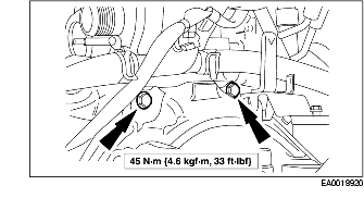
20. Install the LH transaxle mount.
21. Install the engine mount upper bracket.
22. Connect the ground wire.
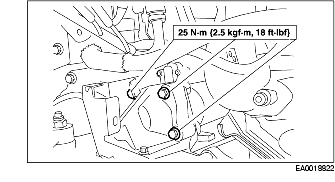
23. Install the rear transaxle mount.
24. Remove the lifting device.
25. Install the speed control unit (if equipped).
26. Position the power steering pump and loosely install the upper bolts.
27. Install the power steering line bracket bolt.
28. Install the power steering line bracket bolt.
29. Position the slave cylinder line and install the clip.
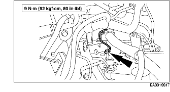
30. Install the clutch slave cylinder bolts.
31. Position the power steering lines and install the bolts.
32. Raise and support the vehicle.
33. Install the lower power steering bolts.
34. Connect the lower radiator hose.
35. Install the engine to transaxle bolts.
36. Install the front transaxle mount through bolt.
37. Connect the block heater electrical connector.
38. Connect the shifter linkages.
39. Install the halfshafts.
40. Install the A/C compressor.
41. Connect the coolant hose.
42. Install the catalytic convertor. (See CATALYTIC CONVERTER REMOVAL/INSTALLATION [YF (2.0L Zetec)].)
43. Connect the heater hoses.
44. Connect the coolant hose.
45. Tighten the upper power steering pump bolts to specification.
46. Connect the upper radiator hose.
47. Connect the evaporative emission (EVAP) canister vacuum lines.
48. Connect the power distribution box electrical connections.
49. Connect the wire harness electrical connector.
50. Connect the ground wire.
51. Connect the powertrain control module (PCM) wire harness and ground.
52. Connect the brake booster vacuum supply hose to the intake manifold.
53. Connect the EGR vacuum regulator valve.
54. Connect the throttle cables and speed control cable (if equipped).
55. Connect the fuel line.
56. Install the battery tray. (See BATTERY REMOVAL/INSTALLATION [YF (2.0L Zetec)].)
57. Install the air cleaner assembly. (See AIR CLEANER REMOVAL/INSTALLATION [YF (2.0L Zetec)].)
58. Fill the engine oil.
59. Fill and bleed the engine cooling system. (See ENGINE COOLANT REPLACEMENT [YF (2.0L Zetec)].)
60. Charge the A/C system.
61. Install the hood.