1. Remove in the order indicated in the table.
2. Install in the reverse order of removal.
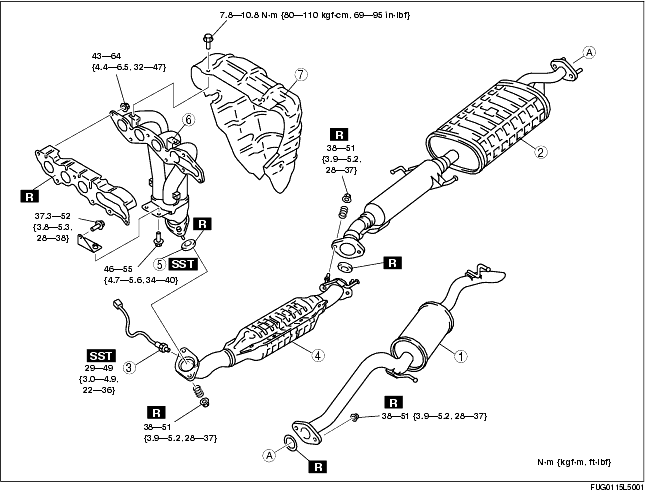
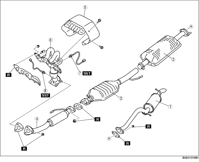
R.H.D. model
|
1
|
After-silencer
|
|
2
|
Main silencer
|
|
3
|
HO2S
(See HO2S Removal Note.)
|
|
4
|
Catalytic converter
|
|
5
|
Seal ring
|
|
6
|
Exhaust manifold
|
|
7
|
Exhaust manifold insulator
|
L.H.D. model
|
1
|
After-silencer
|
|
2
|
Main silencer
|
|
3
|
Presilencer
|
|
4
|
Front pipe
|
|
5
|
Exhaust manifold insulator
|
|
6
|
Exhaust manifold
|
|
7
|
Front HO2S
(See HO2S Removal Note.)
|
|
8
|
Rear HO2S
(See HO2S Removal Note.)
|
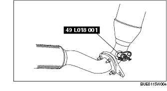
1. Remove the HO2S using the SST.
1. Remove the seal ring using a flathead screwdriver being careful not to damage the pipe.
1. Remove the transverse member. (See FRONT CROSSMEMBER REMOVAL/INSTALLATION.)
2. Remove the splash shield.
3. Remove the under cover.
4. Remove the front pipe.
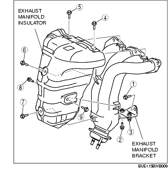
1. Loosen the exhaust manifold insulator bolts.
2. Position the generator out of the way, then position the exhaust manifold insulator out of the way. (See GENERATOR REMOVAL/INSTALLATION [L3 R.H.D.].)
3. Loosen the exhaust manifold nuts and bolts.
4. Lower the exhaust manifold.
5. Remove the exhaust manifold insulator.
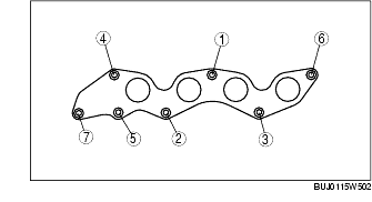
1. Tighten the exhaust manifold installation bolts in the order shown in the figure.
2. Tighten the exhaust manifold bracket and exhaust manifold insulator installation bolts in the order shown in the figure.
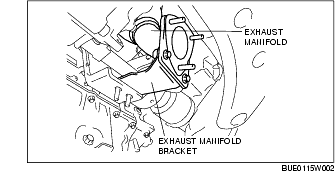
1. Temporarily install and lightly tighten the exhaust manifold to the exhaust manifold bracket.
2. Tighten the exhaust manifold installation bolts in the order shown in the figure.
3. Tighten the exhaust manifold bracket installation bolts and nuts.
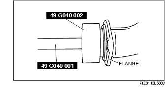
1. Temporarily install the seal ring to the pipe so that the seal ring is even with the flange.
2. Install the SST to the seal ring so that the SST is even with the flange.
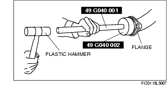
3. Press in the seal ring by tapping the SST using a plastic hammer until the seal ring contacts the flange.