Diagnostic Procedure
|
STEP
|
INSPECTION
|
ACTION
|
|
|---|---|---|---|
|
1
|
INSPECT PID FOR OUTPUT ERROR FROM ABS WHEEL-SPEED SENSOR USING WDS OR EQUIVALENT
• Turn the ignition switch off.
• Connect the WDS or equivalent to the DLC-2.
• Select the following PIDs using the WDS or equivalent:
LF_WSPD
LR_WSPD
RF_WSPD
RR_WSPD
• Drive the vehicle.
• Verify that the vehicle speeds detected by the four ABS wheel-speed sensors are approximately the same.
• Are the vehicle speeds approximately the same?
|
Yes
|
Go to Step 3.
|
|
No
|
Go to the next step.
|
||
|
2
|
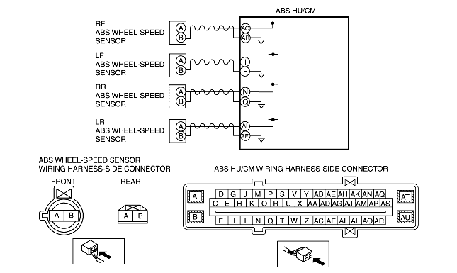
INSPECT FOR SHORT TO GROUND BETWEEN ABS WHEEL-SPEED SENSOR AND GROUND
• Disconnect the ABS wheel-speed sensor connector.
• Inspect for no continuity between the following ABS wheel-speed sensor connector terminals (vehicle wiring harness-side) and body ground:
• Is the continuity normal?
|
Yes
|
Go to the next step.
|
|
No
|
Repair or replace the wiring harness, then go to Step 6.
|
||
|
3
|
INSPECT IF MALFUNCTION OCCURRED DUE TO IMPROPER SENSOR CLEARANCE.
• Inspect the clearance between the ABS wheel-speed sensor and the ABS sensor rotor.
• Is the clearance normal?
|
Yes
|
Go to the next step.
|
|
No
|
Replace the ABS wheel-speed sensor, then go to Step 6.
|
||
|
4
|
VISUALLY INSPECT ABS SENSOR ROTOR FOR FOREIGN MATERIAL ADHERING OR IMPROPER INSTALLATION
• Is the result normal?
|
Yes
|
Go to the next step.
|
|
No
|
Replace the ABS sensor rotor, then go to Step 6.
|
||
|
5
|
INSPECT IF MALFUNCTION OCCURRED DUE TO INTERNAL MALFUNCTION OF HYDRAULIC UNIT (CLOGGING IN PIPING)
• Perform the ABS system operation inspection.
(See ABS SYSTEM INSPECTION [L3].)
• Is the system normal?
|
Yes
|
Go to the next step.
|
|
No
|
Replace the ABS HU/CM, then go to the next step.
(See ABS HU REMOVAL/INSTALLATION.)
|
||
|
6
|
VERIFY THAT THE SAME DTC IS NOT PRESENT
• Clear the DTC from the memory.
(See Clearing DTCs Procedures.)
• Start the engine and drive the vehicle at 10 km/h {6.2 mph} or more.
• Is the same DTC present?
|
Yes
|
Repeat the inspection from Step 1.
If the malfunction recurs, replace the ABS HU/CM.
(See ABS HU REMOVAL/INSTALLATION.)
|
|
No
|
Go to the next step.
|
||
|
7
|
VERIFY THAT NO OTHER DTCs ARE PRESENT
• Are any other DTCs present?
|
Yes
|
Go to the applicable DTC inspection.
(See DTC Table.)
|
|
No
|
DTC inspection completed.
|
||