Diagnostic procedure
|
STEP
|
INSPECTION
|
ACTION
|
|
|---|---|---|---|
|
1
|
VERIFY FREEZE FRAME DATA HAS BEEN RECORDED
• Has the FREEZE FRAME DATA been recorded?
|
Yes
|
Go to the next step.
|
|
No
|
Record the FREEZE FRAME DATA on the repair order, then go to the next step.
|
||
|
2
|
VERIFY RELATED REPAIR INFORMATION AVAILABILITY
• Verify related Service Bulletins and or/on-line repair information availability.
• Is any related repair information available?
|
Yes
|
Perform repair or diagnosis according to the available repair information.
• If the vehicle is not repaired, go to the next step.
|
|
No
|
Go to the next step.
|
||
|
3
|
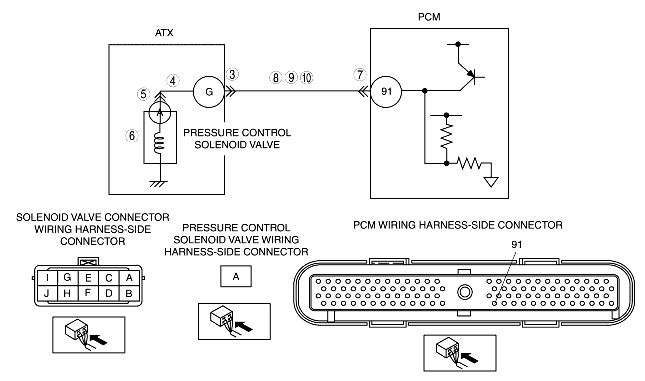
INSPECT SOLENOID VALVE CONNECTOR FOR POOR CONNECTION
• Turn the ignition switch to the LOCK position.
• Disconnect the solenoid valve connector.
• Inspect for poor connection (such as damaged/pulled-out pins, corrosion).
• Is the connection normal?
|
Yes
|
Go to the next step.
|
|
No
|
Repair or replace connector and/or terminals, then go to step 11.
|
||
|
4
|
INSPECT RESISTANCE
• Inspect resistance between solenoid valve connector terminal G (transaxle case side) and body ground.
• Is resistance within 9-18 ohms?
|
Yes
|
Go to Step 7.
|
|
No
|
Go to the next step.
|
||
|
5
|
INSPECT PRESSURE CONTROL SOLENOID CONNECTOR FOR POOR CONNECTION
• Disconnect the pressure control solenoid connector.
• Inspect for poor connection (such as damaged/pulled-out pins, corrosion).
• Is the connection normal?
|
Yes
|
Go to the next step.
|
|
No
|
Repair or replace connector and/or terminals, then go to Step 11.
|
||
|
6
|
INSPECT RESISTANCE
• Inspect resistance between pressure control solenoid terminal A (part-side) and body ground.
• Is resistance within 9-18 ohms?
|
Yes
|
Replace the solenoid harness, then go to Step 11.
|
|
No
|
Verify pressure control solenoid installation.
• If the solenoid is installed correctly, replace the pressure control solenoid, then go to Step 11.
|
||
|
7
|
INSPECT PCM CONNECTOR FOR POOR CONNECTION
• Disconnect the PCM connector.
• Inspect for poor connection (such as damaged/pulled-out pins, corrosion).
• Is the connection normal?
|
Yes
|
Go to the next step.
|
|
No
|
Repair or replace connector and/or terminals, then go to Step 11.
|
||
|
8
|
INSPECT SOLENOID VALVE CONNECTOR CIRCUIT FOR OPEN CIRCUIT
• Inspect for continuity between PCM terminal 91 (wiring harness-side) and solenoid valve connector terminal G (wiring harness-side).
• Is there continuity between terminals?
|
Yes
|
Go to the next step.
|
|
No
|
Repair or replace the wiring harness, the go to Step 11.
|
||
|
9
|
INSPECT SOLENOID VALVE CONNECTOR CIRCUIT FOR SHORT TO POWER SUPPLY
• Turn the ignition switch to the ON position (engine off).
• Inspect the voltage at solenoid valve connector terminal G (wiring harness-side).
• Is the voltage 0 V?
|
Yes
|
Go to the next step.
|
|
No
|
Repair or replace the wiring harness, then go to Step 11.
|
||
|
10
|
INSPECT PCM CIRCUIT FOR SHORT TO GROUND
• Turn the ignition switch to the LOCK position.
• Inspect for continuity between PCM terminal 91 (wiring harness-side) and body ground.
• Is there continuity?
|
Yes
|
Repair or replace the wiring harness, then go to the next step.
|
|
No
|
Go to the next step.
|
||
|
11
|
VERIFY TROUBLESHOOTING OF DTC P0745 COMPLETED
• Make sure to reconnect all the disconnected connectors.
• Clear the DTC from memory using the WDS or equivalent.
• Driving in 1GR at D range.
• Are any DTCs present?
|
Yes
|
Replace the PCM, then go to the next step.
|
|
No
|
Go to the next step.
|
||
|
12
|
VERIFY AFTER REPAIR PROCEDURE
• Perform the "After Repair Procedure".
• Are any DTCs present?
|
Yes
|
Go to the applicable DTC inspection.
(See DTC TABLE [GF4AX-EL].)
|
|
No
|
DTC troubleshooting completed.
|
||