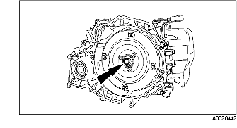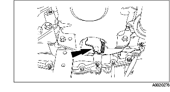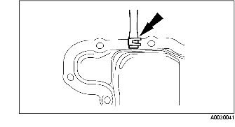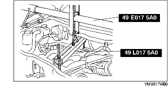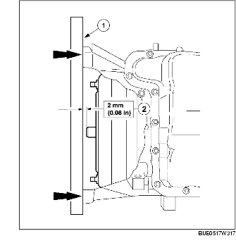
1. Inspect the installation depth of the torque converter.
2. Lubricate the torque converter pilot hub with the grease.
3. Position the transaxle in place.
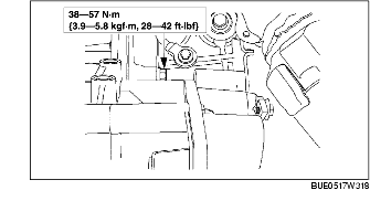
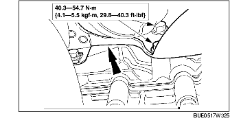
4. Move the transaxle complete toward the engine complete and install the bolt.
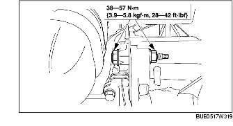
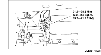
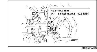
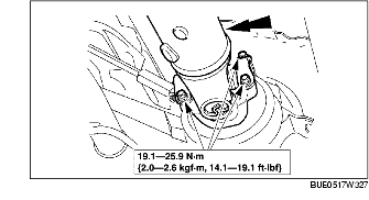
5. Install the bolt.
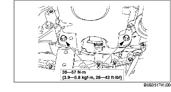
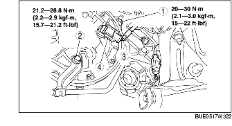
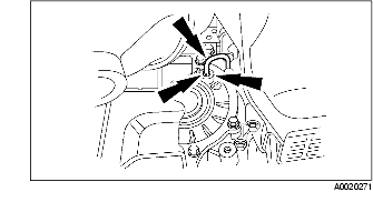
6. Install the bolts.
7. Remove the transaxle jack.
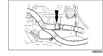
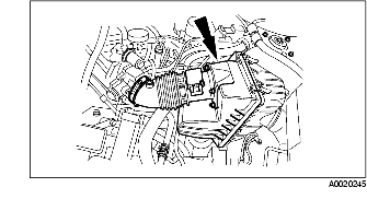
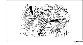
8. Install the oil hose.
9. Install the following parts.
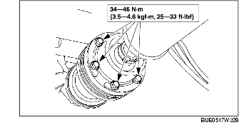
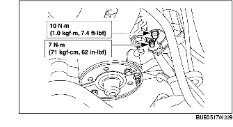
10. Install four torque converter mounting nuts.
11. Install the access cover.
12. Connect the main control cover tube.
13. Lower the vehicle.
14. Raise the transaxle enough to install the cross brace.
15. Lift up the vehicle.
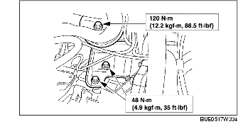
16. Install the cross brace.
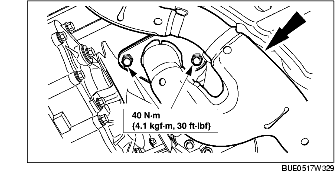
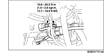
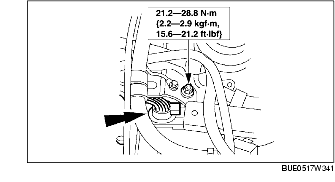
17. Install the bracket and tighten bolt.
18. Install the bolts.
19. Press the two tabs and install the transfer vent tube.
20. Install the propeller shaft and install the four rear propeller shaft bolts.
21. Install the front propeller shaft bolts.
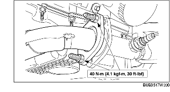
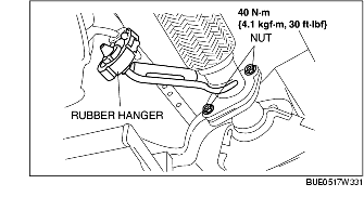
22. Install the exhaust pipe and connect the exhaust pipe flange.
23. Connect the front flange.
24. Install the exhaust pipe.
25. Install the cross brace.
26. Install the drive shaft component (LH). (See FRONT DRIVE SHAFT REMOVAL/INSTALLATION.)
27. Install the drive shaft (RH) and joint shaft component. (See FRONT DRIVE SHAFT REMOVAL/INSTALLATION.) (See JOINT SHAFT REMOVAL/INSTALLATION [YF (2.0 L Zetec), AJ (3.0 L Duratec)].)
28. Install the two splash shields.
29. Install both front wheels. (See WHEEL AND TIRE REMOVAL/INSTALLATION.)
30. Lower the vehicle.
31. Lower the engine onto the engine mount (RH).
32. Install the bolt for the engine mount (RH).
33. Install the rear transaxle mount.
34. Install the transaxle mount component.
35. Install the bolt.
36. Remove the SSTs.
37. Connect the connectors to the valve cover.
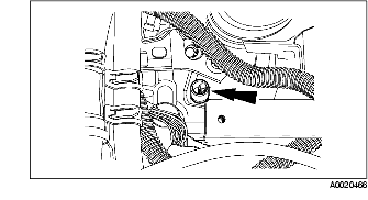
38. Install the power steering pressure hose bracket.
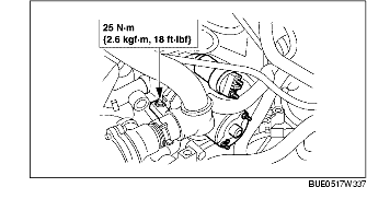
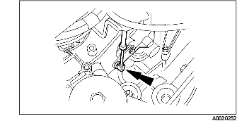
39. Install the starter and install the bolt.
40. Install the thermostat housing. (See THERMOSTAT REMOVAL/INSTALLATION [YF (2.0L Zetec)].) (See THERMOSTAT REMOVAL/INSTALLATION [AJ (3.0L Duratec)].)
41. Install the ground wiring harness.
42. Install the starter wiring harness connector.
43. Install the selector cable and bracket.
44. Connect the selector cable.
45. Connect the wiring harness.
46. Install the wiring harness bracket spacer.
47. Install the wiring harness bracket and connect the transaxle wiring harness connector.
48. Connect the HO2S sensor connector.
49. Connect the HO2S sensor connectors.
50. Connect the TR switch connector.
51. Align the TR switch using the SST.
52. Install the air cleaner component.
53. Install the air hose and air cleaner cover.
54. Connect the crankcase vent hose and MAF sensor connector.
55. Verify that there is no blockage or kinks, and the vent hose routing is correct.
56. Install the battery and battery tray. (See BATTERY REMOVAL/INSTALLATION [YF (2.0L Zetec)].) (See BATTERY REMOVAL/INSTALLATION [L3, AJ (3.0L Duratec)].)
57. Connect the negative battery cable.
58. Add the engine coolant. (See ENGINE COOLANT REPLACEMENT [YF (2.0L Zetec)].) (See ENGINE COOLANT REPLACEMENT [AJ (3.0L Duratec)].)