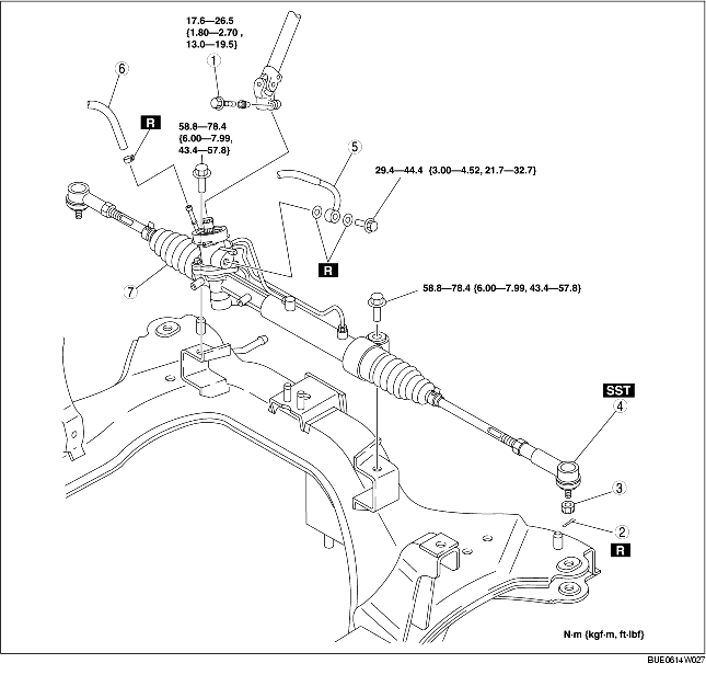
1. Remove the footrest, set plate, and dust boot.
2. Remove the stabilizer control link nut and disconnect the stabilizer control link from the shock absorber.
3. Remove the No.1 engine mount rubber and No.1 engine bracket. (See ENGINE REMOVAL/INSTALLATION [L3].)
4. Remove in the order indicated in the table.
5. Install in the reverse order of removal.
6. After installation, inspect the toe-in and steering angle, and adjust if necessary. (See FRONT WHEEL ALIGNMENT.)
|
1
|
Bolt (universal joint)
|
|
2
|
Cotter pin
|
|
3
|
Nut
|
|
4
|
Tie-rod end
(See Tie-rod End Removal Note.)
|
|
5
|
Pressure pipe
|
|
6
|
Return hose
|
|
7
|
Steering gear and linkage
|
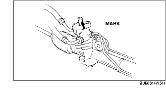
1. Place an alignment mark on the pinion shaft and gear housing for proper installation and remove the bolt.
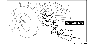
1. Detach the tie-rod end from the steering knuckle using the SST.
1. Align the alignment marks on the pinion shaft and gear housing, and tighten the bolt.