Purpose and Location
LH Control Unit Diagram For Right Cylinder (1-6) Bank:
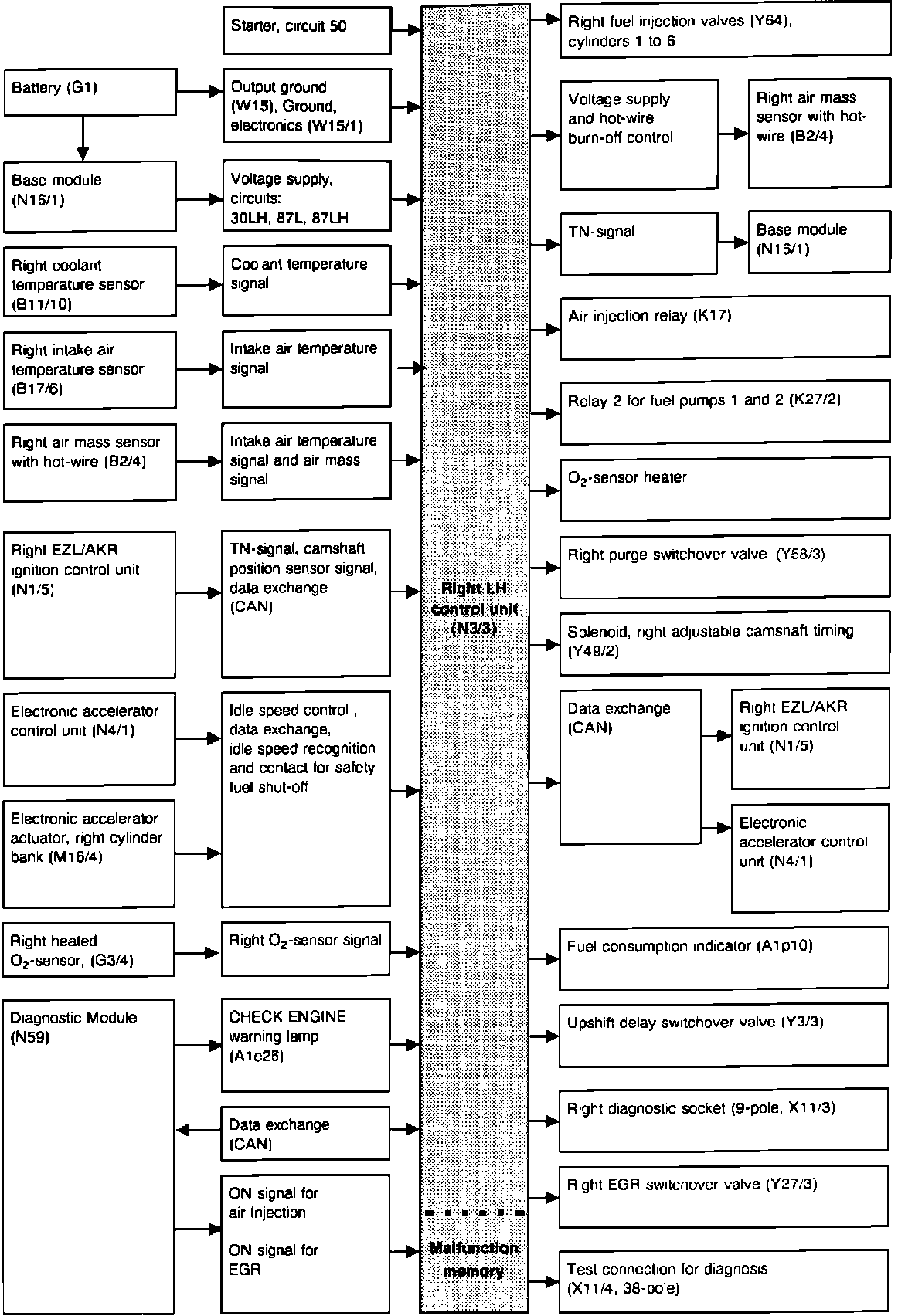
RIGHT CYLINDER (1-6) BANK
LH Control Unit Diagram For Left Cylinder (7-12) Bank:
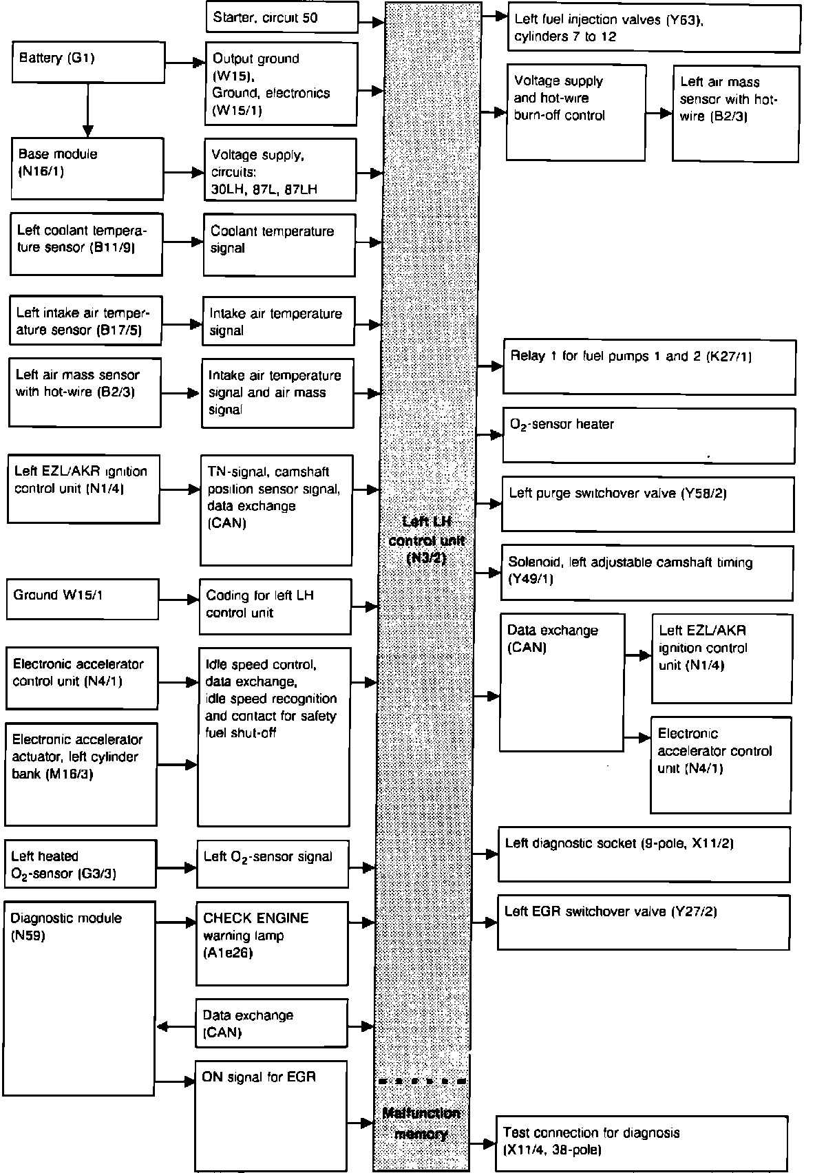
LEFT CYLINDER (7-12) BANK
PURPOSE
The two LH Control modules (N3/2 and N3/3) have a microprocessor that receives signals from various input devices regarding engine operating conditions. This information is evaluated in relation to pre-programmed values and calculates the correct injector frequency (opening duration and injection timing) to provide optimum performance, economy, and the least emissions output.
Two separate fuel injection systems (one control module per system) are required. One system operates cylinders 1 through 6 and the other cylinders 7 through 12.
LH Control Unit Location:
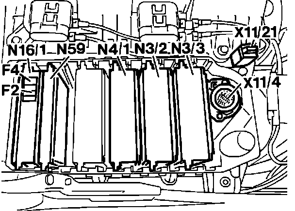
LOCATION AND I.D.
The control module for the right cylinder (1-6) bank (N3/3) is located in the module box in engine compartment, passenger side firewall. The control module connector is color coded dark green/light green.
The control module for the left cylinder (7-12) bank (N3/3) is located in the module box in engine compartment, passenger side firewall. The control module connector is color coded dark blue/light blue.