Exhaust Gas Recirculation: Description and Operation
Fig. 221 EGR system (all Calif. vehicles, and Fed. 2.0L) *** UPDATED BY STB 8325001:
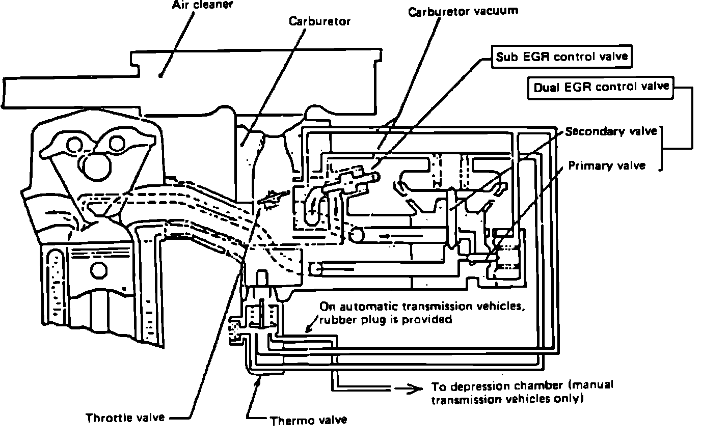
Exhaust gas recirculation, Fig. 221 is used to reduce oxides of nitrogen emissions in the vehicle exhaust. EGR uses partial recirculation of the exhaust gases from a port in the cylinder head to a port in the intake manifold.
*** UPDATED BY STB 8325001 APRIL 1983
Fig. 14 Dual EGR valve:
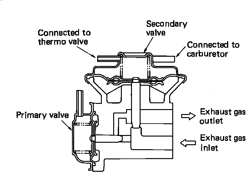
The dual EGR valve system used on California vehicles and Federal vehicles with 2.0L engines, consists of primary and secondary EGR valves, Fig. 14. Each valve is controlled by different port vacuums in response to throttle valve setting. The primary valve controls EGR flow for vehicle operation within a relatively narrow range of low throttle valve settings. The secondary control valve allows recirculation of exhaust gas when the throttle valve is further open. Vacuum applied to the dual EGR control valve is controlled by the thermo valve.
Fig. 33 Sub-EGR control valve:

EGR flow is suspended at idle by the sub EGR valve, Fig. 33 and at full throttle by the lack of port vacuum.
Fig. 9 Thermo valve ***UPDATED BY STB 8325001 APRIL 1983:
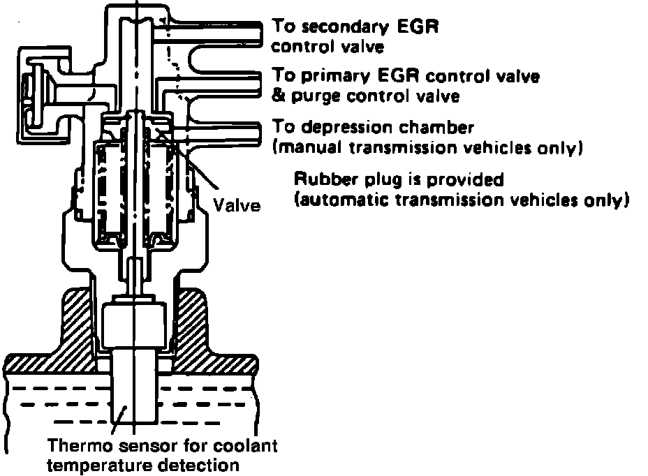
THERMO VALVE
A Thermo valve, Fig. 9 is incorporated in the EGR system to sense coolant temperature at the intake manifold. The thermo valve prevents the EGR control valve from opening when coolant temperature is lower than a pre-set value eliminating driveability problems when the engine is cold.