California
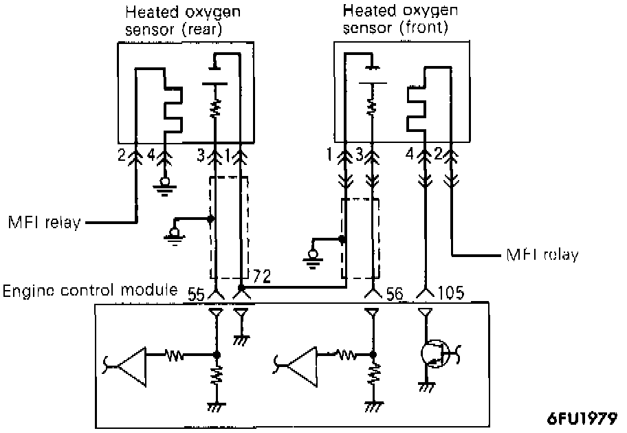
CIRCUIT DIAGRAM
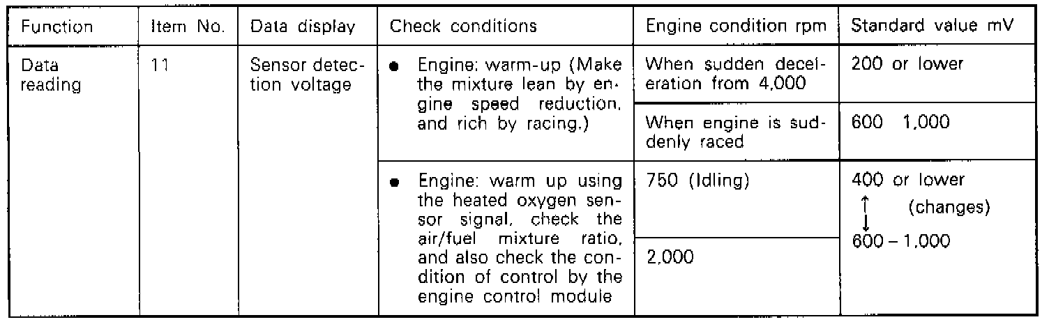
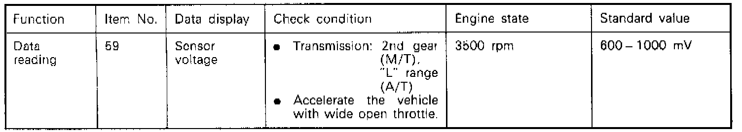
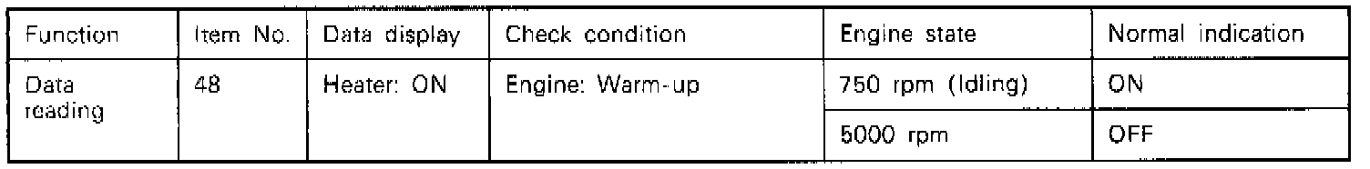
INSPECTION USING SCAN TOOL
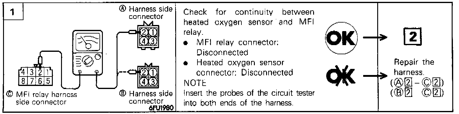
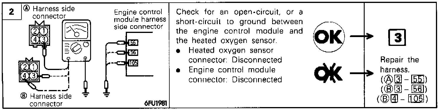
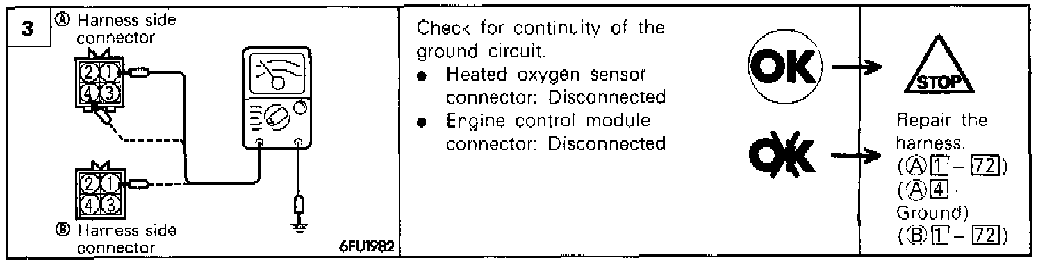
HARNESS INSPECTION PROCEDURE
COMPONENT TEST PROCEDURE
1. Disconnect the heated oxygen sensor (front) connector and connect the special tool (test harness) to the oxygen sensor (front) connector.
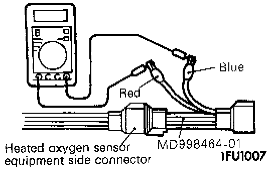
2. Check that there is continuity [approximately 20 Ohms at 20°C (68°F)] across terminals 2 (red clip of the special tool) and 4 (blue clip) of the heated oxygen sensor (front) connector.
3. If there is no continuity, replace the heated oxygen sensor (front).
4. Warm up the engine until the engine coolant temperature becomes 80°C (176°F) or higher.
5. Using jumper wires, connect terminals 2 (red clip of the special tool) and 4 (blue clip) of the heated oxygen sensor connector to battery + and - terminals respectively. CAUTION Ensure that the jumper wires are connected correctly. as wrong connections result in a broken heated oxygen sensor.
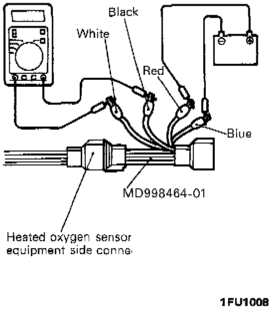
6. Connect a digital voltmeter across terminals 1 (black clip of the special tool) and 3 (white clip).
7. Race the engine repeatedly and measure the output voltage of the heated oxygen sensor (front).
Output Voltage, Engine Raced: 0.6 - 1.0 Volts
8. If the measurements are not as specified, detective heated oxygen sensor (front) is suspected.
NOTE: When the air-fuel mixture becomes richer as a result of repeated racing. the heated oxygen sensor should output a voltage of 0.6 - 1.0 Volts.
TROUBLESHOOTING HINTS
- The exhaust gas purification performance will worsen if there is a malfunction of the heated oxygen sensor .
- If the heated oxygen sensor output voltage deviates from the standard value even though the results of the checking of the heated oxygen sensor are normal, the cause is probably a malfunction of a component related to mixture control.
[Examples]
- Malfunction of an injector.
- Air leakage into the intake manifold from a leaking gasket.
- Malfunction of the volume air flow sensor, the intake air temperature sensor, the barometric pressure sensor, or the engine coolant temperature sensor.