California
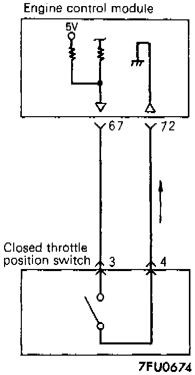
CIRCUIT DIAGRAM

INSPECTION USING SCAN TOOL
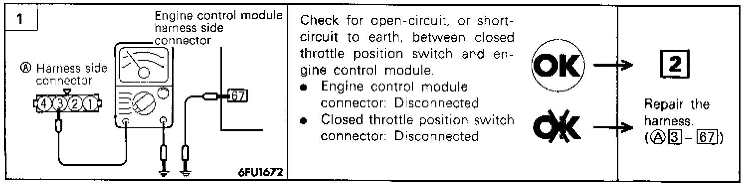
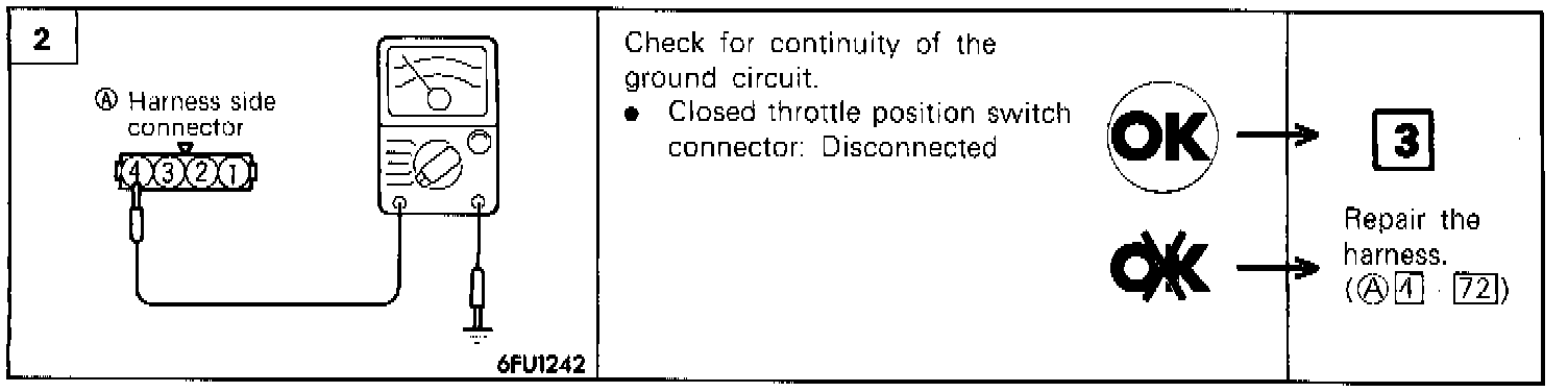
HARNESS INSPECTION PROCEDURE
COMPONENT TEST PROCEDURE
1. Disconnect the throttle position sensor connector.
2. Check the continuity between the throttle position sensor connector side terminal 3 and terminal 4.
Released: Conductive (0 Ohms)
Depressed: Non-conductive (infinite Ohms)
3. The closed throttle position switch is part of the throttle position sensor. If out of specification, replace the throttle position sensor.
NOTE: After replacement the throttle position sensor should be adjusted.
TROUBLESHOOTING HINTS
- If there is an abnormal condition of the closed throttle position switch output even though the results of the checking of the closed throttle position switch harness and of the component itself indicate a normal condition, the cause may be presumed to be one of the following.
- Improper adjustment of the accelerator cable or the cruise-control cable.
- Improper adjustment of the fixed speed adjusting screw.