With California Emissions
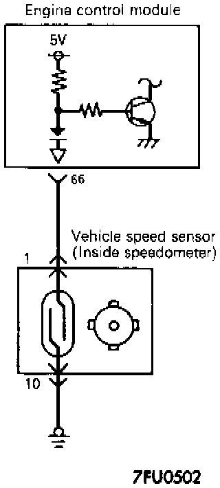
CIRCUIT DIAGRAM
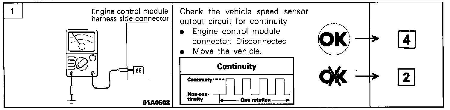
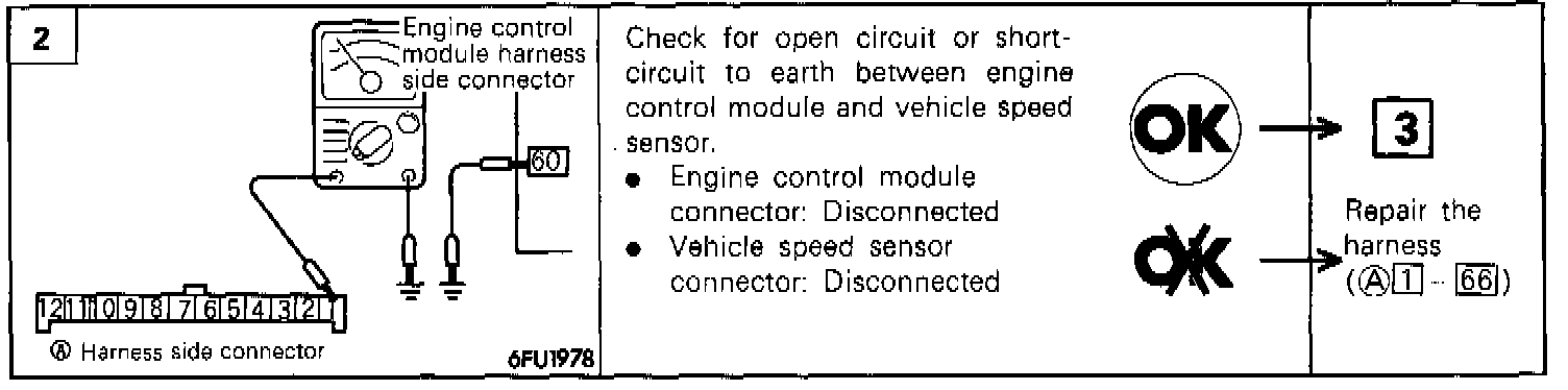
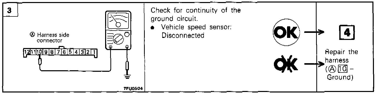
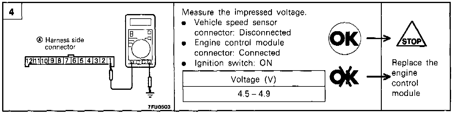
HARNESS INSPECTION PROCEDURE
COMPONENT TEST PROCEDURE
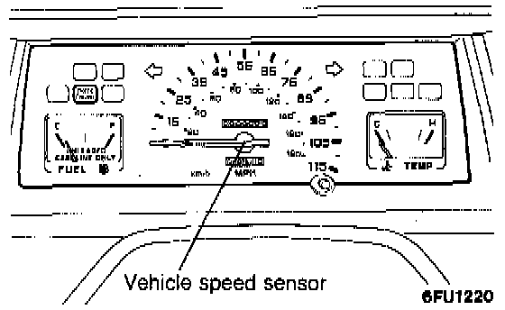
1. Connect a ohmmeter set to the 1X Ohm range or a digital multitester across the reed switch positive (+) and negative (-) terminals and turn the speedometer slowly.
2. It is normal for continuity and discontinuity between the terminals to alternate four times for each revolution of the shaft.
3. If not, replace the speedometer assembly.
TROUBLESHOOTING HINTS
- If there is damaged or disconnected wiring, or a short-circuit, of the vehicle-speed sensor signal circuit, the engine may stall when the vehicle speed is reduced and the vehicle is stopped.