Inspection Procedure 1
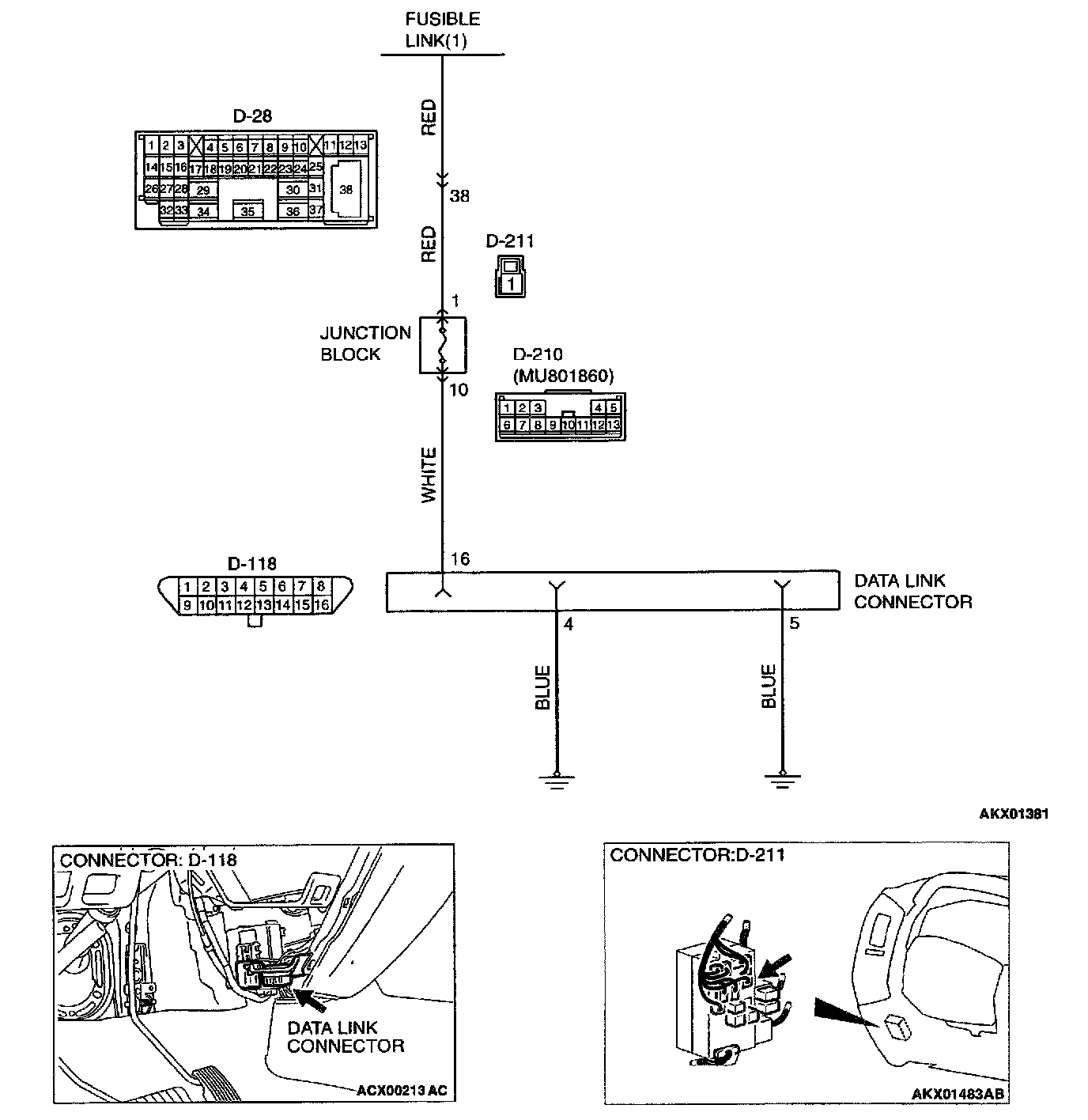
Connectors:
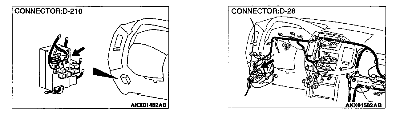
CIRCUIT OPERATION
- A battery positive voltage is applied on the data link connector power terminal (terminal 16). The ground terminals (terminal 4, 5) are grounded to the vehicle body.
COMMENT
- The cause is probably a defect in power supply system (including ground) for the on-board diagnostic test mode line.
TROUBLESHOOTING HINTS (The most likely causes for this case:)
- Malfunction of the data link connector.
- Damaged harness wire.
DIAGNOSIS
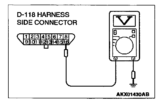
STEP 1. Check the power supply voltage at data link connector D-118.
1. Measure voltage between terminal 16 and ground.
- Voltage should be battery positive voltage.
Q: Is the voltage normal?
YES: Go to step 2.
NO: Check harness connectors D-210, D-211, D-28 at intermediate connector for damage, and repair or replace as required. Refer to Harness Connector Inspection. If intermediate connector D-210, D-211, D-28 are in good condition, repair an open circuit between fusible link (6) and data link connector D-118 terminal 16. Then confirm that the malfunction symptom is eliminated.
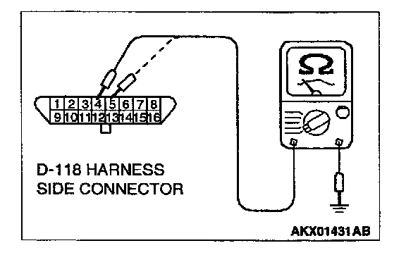
STEP 2. Check the continuity at data link connector D-118.
1. Check for the continuity between terminal 4, 5 and ground. Should be less than 2 ohm
Q: Is the continuity normal?
YES: Replace the scan tool. Then confirm that the malfunction symptom is eliminated.
NO: Repair an open circuit or harness damage between data link connector D-118 terminal 4, Sand ground. Then confirm that the malfunction symptom is eliminated.