Inspection Procedure 2
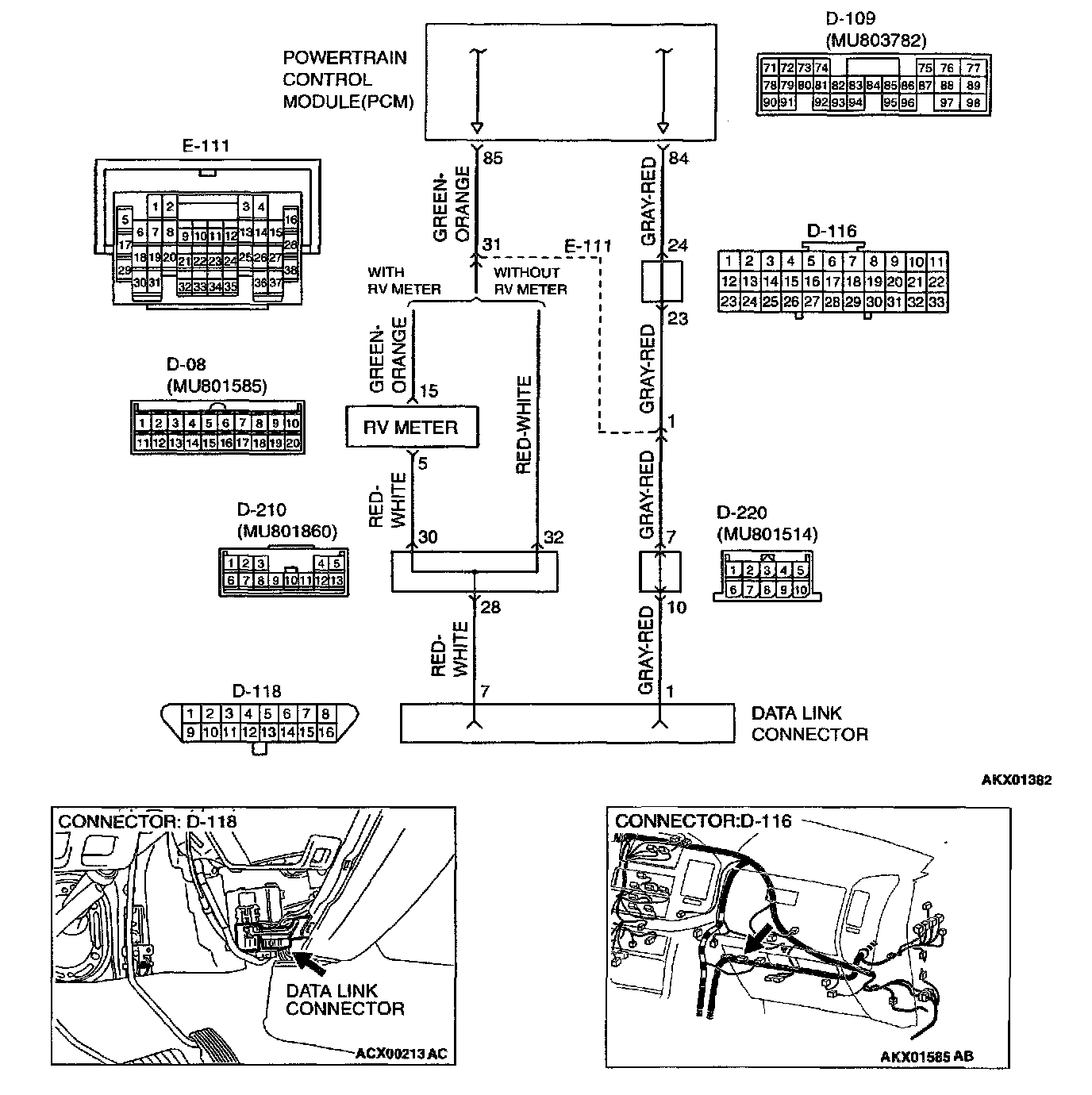
Connectors:
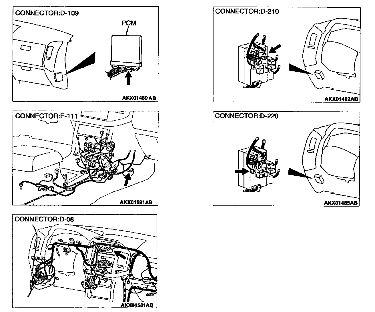
CIRCUIT OPERATION
- A diagnostic output is made from the PCM (terminal 85) to the diagnostic output terminal (terminal 7) of the data link connector.
- When diagnostic test mode control terminal (terminal 1) of the data link connector is grounded, the PCM (terminal 84) changes to the diagnostic test mode.
COMMENT
- No power supply to PCM.
- Detective ground circuit of PCM
- Detective PCM.
- Improper communication line between PCM and scan tool.
TROUBLESHOOTING HINTS (The most likely causes for this case:)
- Malfunction of PCM power supply circuit.
- Malfunction of the PCM.
- Open circuit between PCM and data link connector.
DIAGNOSIS
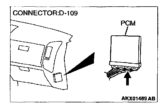
STEP 1. Check harness connector D-109 at PCM for damage.
Q: Is the harness connector in good condition?
YES: Go to Step 2.
NO: Repair or replace it. Refer to Harness Connector Inspection. Then confirm that the malfunction symptom is eliminated.
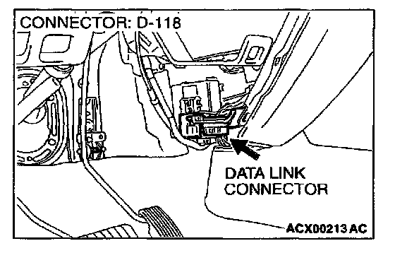
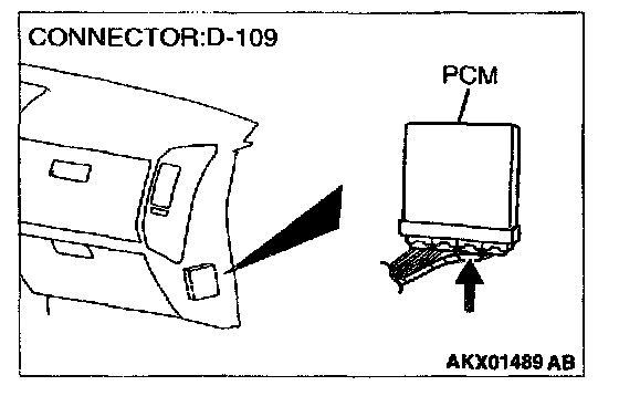
STEP 2. Check for open circuit, short circuit to ground and harness damage between data link connector D-118 terminal 1 and PCM connector D-109 terminal 84.
NOTE: Check harness after checking intermediate connectors D-220, E-111, D- 116. If intermediate connector D-220, E-111, D-116 are damaged, repair or replace them. Refer to Harness Connector Inspection. Then check that the malfunction is eliminated.
Q: Is the harness wire in good condition?
YES: Go to Step 3.
NO: Repair it. Then confirm that the malfunction symptom is eliminated.
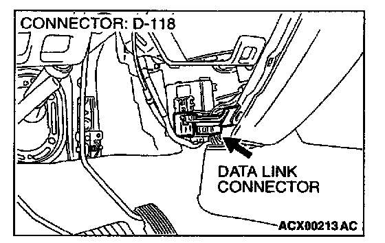
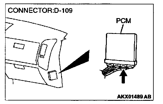
STEP 3. Check for open circuit, short circuit to ground and harness damage between data link connector D-118 terminal 7 and PCM connector D-109 terminal 85.
NOTE: Check harness after checking intermediate connectors D-29, D-08, E-111. If intermediate connector D-29, D-08, E-111 are damaged; repair or replace them. Refer to Harness Connector Inspection. Then check that the malfunction is eliminated.
Q: Is the harness wire in good condition?
YES: Refer to, INSPECTION PROCEDURE 28- Power Supply System and Ignition Switch-IG System.
NO: Repair it. Then confirm that the malfunction symptom is eliminated.