Air Bag Module(s) and Clock Spring
REMOVAL AND INSTALLATIONWARNING:
- Never attempt to disassemble or repair the air bag modules or clock spring. If faulty, replace it.
- Do not drop the air bag modules or clock spring or allow contact with water, grease or oil.
- Replace it if a dent, crack, deformation or rust is detected.
- The air bag modules should be stored on a flat surface and placed so that the pad surface is facing upward. Do not place anything on top of it.
- Do not expose the air bag modules to temperatures over 93 °C (200 °F).
- After deployment of an air bag, replace the air bag modules. Check the clock spring and if faulty, replace it with a new part.
- Wear gloves and safety glasses when handling air bags that have already deployed.
- An undeployed air bag module should only be disposed of in accordance with the procedures described.
For removal and installation of the front seatback assembly with side air bag module, refer to Front seat.
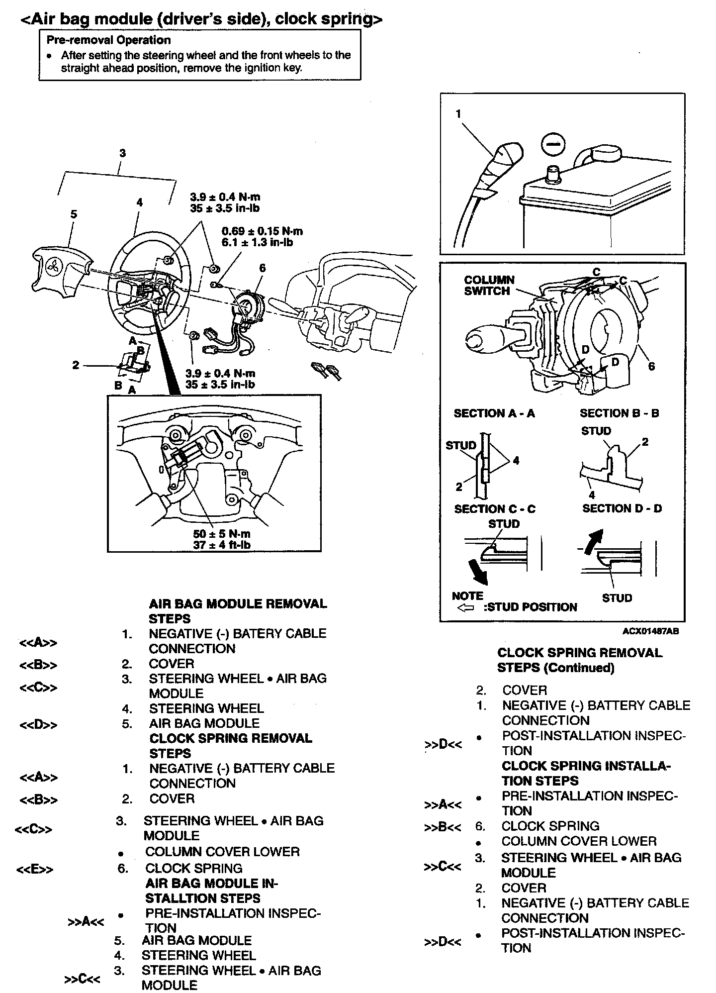
Air Bag Module (Driver's Side), Clock Spring:
Required Special Tools:
MB990784: Ornament Remover
MB991223 (MB991222): Harness Set (Probe)
MB991502: Scan Tool (MUT-II)
MB991613: SRS Check Harness
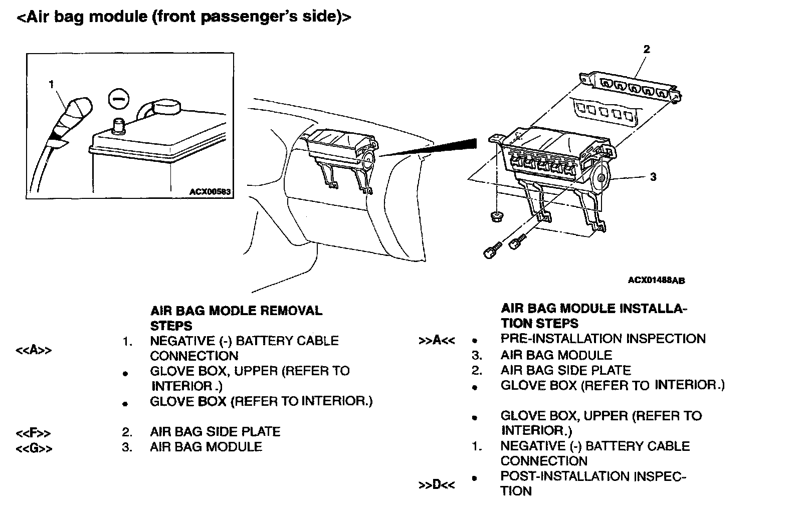
Air Bag Module (Front Passenger's Side):
Required Special Tool:
MB991502: Scan Tool (MUT-II)
REMOVAL SERVICE POINTS

[[A]] NEGATIVE (-) BATTERY CABLE DISCONNECTION
DANGER: Wait at least 60 seconds after disconnecting the battery cable be for doing any further work.
WARNING: Battery posts, terminals and related accessories contain lead and lead compounds. WASH HANDS AFTER HANDLING.
Disconnect the negative (-) battery cable from the battery and tape the terminal to prevent accidental connection and air bag(s) deployment.
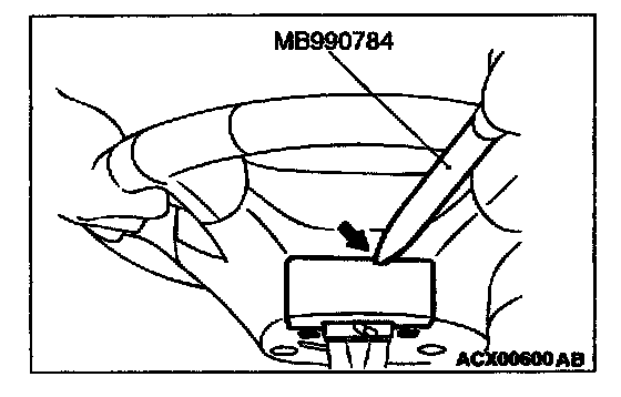
[[B]] Removal of cover
Insert the special tool from the position as shown by the arrow in the illustration to remove the cover.
NOTE: There is a cutout for tool insertion at the inside of position shown in the illustration.
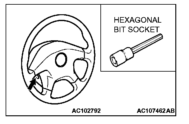
[[C]] Removal of steering wheel air bag module assembly
1. Remove the air bag module and the horn switch connector through the hole appeared after removing the steering wheel cover.
2. Loosen the bolt completely before removing the steering wheel assembly.
NOTE: We recommend to use the commercial hex bit socket or the hexagonal wrench which effective length of hexagonal portion is 75 mm (3.0 in.) and over and which width across flats is 8 mm (0.3 in.).
Recommended tool: Hex bit socket 8 mm (0.3 in.) (Type: 3010M-160, 4010M-160) made by KOKEN
[[D]] Removal of air bag module (driver's side)
CAUTION:
- Do not diagnose the circuit using an electric circuit tester or disassemble the air bag module.
- Keep the removed driver's seat side air bag module at the clean and dry place turning the pad face up.
[[E]] Removal of clock spring
CAUTION: Keep the removed clock spring at the clean and dry place.
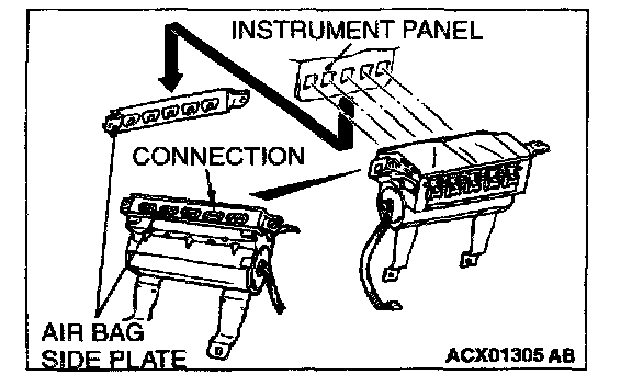
[[F]] Removal of air bag side plate
1. After removing the mounting bolt of the air bag side plate, slide the plate downward to disconnect the interfit with the front passenger's side seat air bag module.
2. After removing the mounting bolts and nuts of the front passenger's side seat air bag module, slide the front passenger's side seat air bag module crosswise to remove the air bag side plate.
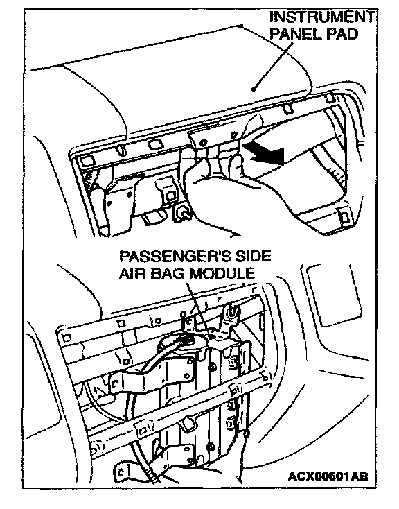
[[G]] Removal of air bag module (front passenger's side)
CAUTION: Keep the front passenger's side seat air bag module at the clean and dry place turning the inflating face up.
While pulling the portion shown in the illustration on the instrument panel pad toward you, remove the front passenger's side air bag module to pull it out from down side.
INSTALLATION SERVICE POINTS
]]A[[ PRE-INSTALLATION INSPECTION
WARNING: Dispose of air bag modules only according to the specified procedure on.
1. When installing the new air bag modules and clock spring, refer to "INSPECTION".
2. Connect the negative (-) battery cable.
CAUTION: Turn "OFF" the ignition switch before connecting or disconnecting scan tool MB991502.
3. Connect scan tool MB991502 to the data rink connector.
4. Turn the ignition key to the "ON" position.
5. Conduct diagnostic test using scan tool MB991502 to ensure entire SRS system operates properly.
DANGER: Wait at least 60 seconds after disconnecting the battery cable be for doing any further work.
WARNING: Battery posts, terminals and related accessories contain lead and lead compounds. WASH HANDS AFTER HANDLING.
6. Turn the ignition key to the "OFF" position. Disconnect the negative (-) battery cable and tape the terminal to prevent accidental connection and an bag deployment.

]]B[[ CLOCK SPRING INSTALLATION
WARNING: Ensure that the clock spring's mating marks are properly aligned. If not, the steering wheel may not rotate completely during a turn, or the flat harness in the clock spring could be damaged. This would present normal SRS operation and possibly cause serious injury to the driver.
Align the mating marks of the cock spring. Turn the front wheels to the straight-ahead position. Then install the clock spring to the column switch.
Mating Mark Alignment
Turn the dock spring clockwise fully. Then turn it back approximately 3 turns counterclockwise to align the mating marks.
]]C[[ STEERING WHEEL.AIR BAG MODULE INSTALLATION
CAUTION: When installing the steering wheel, ensure that the harness of the clock spring does not become caught or tangled.
1. Before installing the steering wheel, turn the vehicle's front wheels to the straight-ahead position and align the mating marks of the clock spring.
2. After securing the steering wheel, turn the steering wheel all the way in both directions to confirm that the steering wheel rotation is normal.

]]D[[ POST-INSTALLATION INSPECTION
1. Reconnect the negative (-) battery cable.
2. Turn the ignition key to the "ON" position.
3. Does the "SRS" warning light illuminate for approximately seven seconds, and the remain off for at least five seconds after turning "OFF"?
4. If yes, the SRS system is functioning properly. If no, consult SRS WARNING LIGHT CHECK.