Inspection Procedure 28
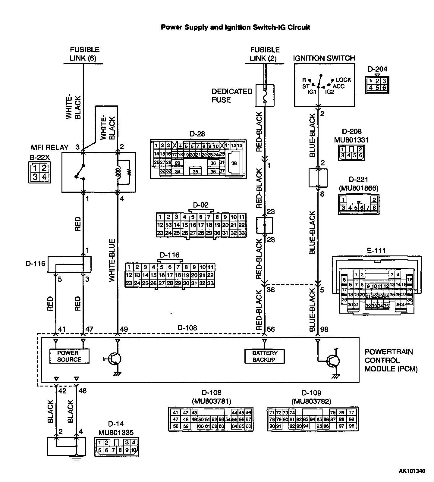
Power Supply And Ignition Switch-IG Circuit:
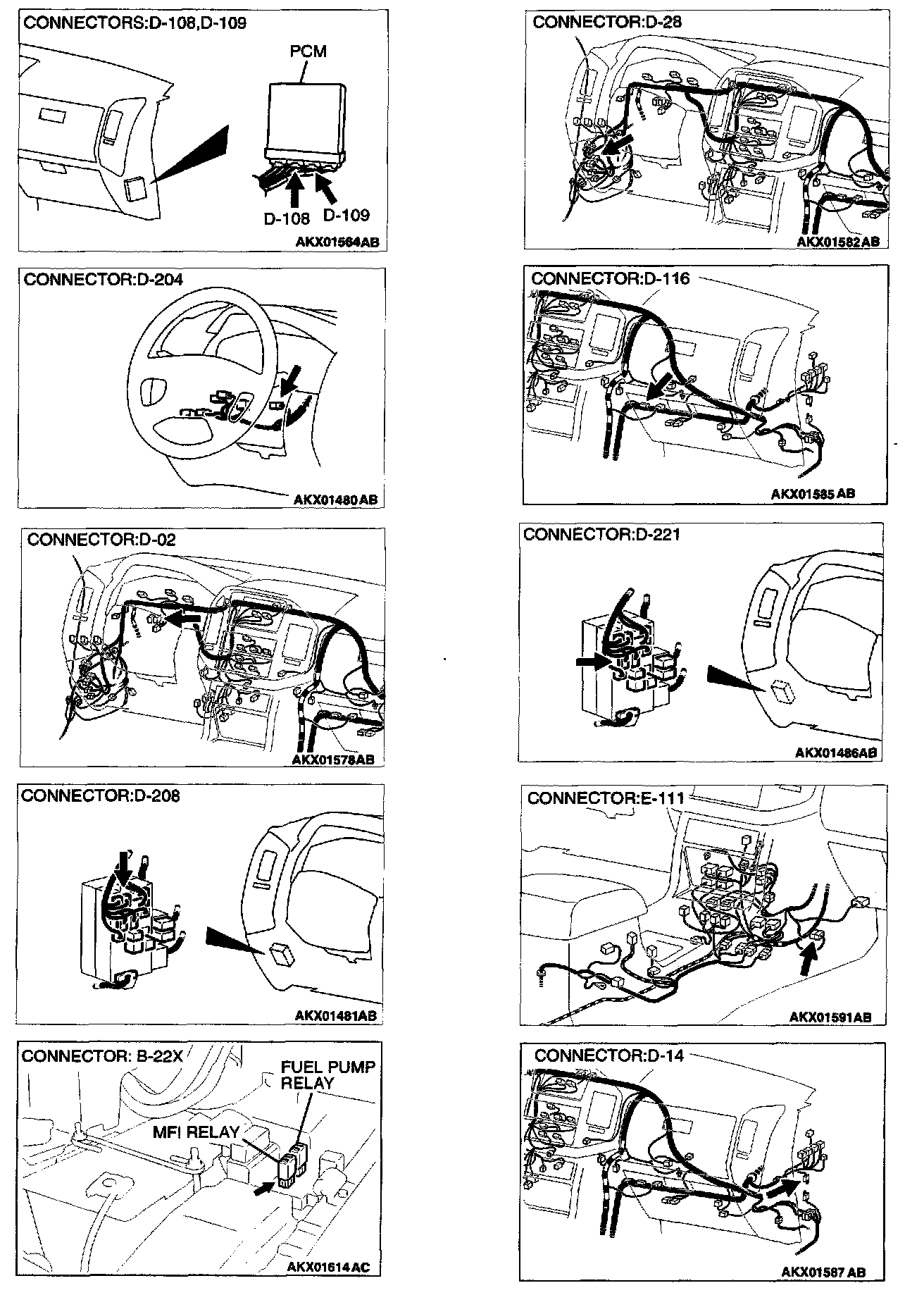
Connectors:
CIRCUIT OPERATION
- Battery positive voltage is applied to the MFI relay (terminals 2, 3).
- When the ignition switch is turned to the "ON" position, the battery positive voltage is applied to the PCM (terminal 98).
When the battery positive voltage is applied, the PCM turns the power transistor in the PCM "ON" and grounds the MFI relay coil, with this, the MFI relay turns "ON" and the battery positive voltage is supplied to the PCM (terminal 41, 47) from the MFI relay (terminal 1).
- Battery positive voltage is constantly supplied to the PCM (terminal 66) as the backup power.
- The or PCM (terminals 42, 48) is grounded to the vehicle body.
TROUBLESHOOTING HINTS (The most likely causes for this code to be set are:)
- Malfunction of the ignition switch.
- Malfunction of the MFI relay.
- Improper connector contact, open circuit or short- circuited harness wire.
- Disconnected PCM ground wire.
- Malfunction of the PCM.
DIAGNOSIS
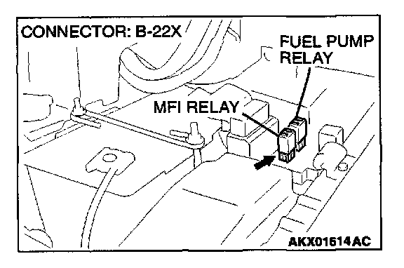
STEP 1. Check harness connector B-22X at MFI relay for damage.
Q: Is the harness connector in good condition?
YES: Go to Step 2.
NO: Repair or replace it. Refer to Harness Connector Inspection. Then confirm that the malfunction symptom is eliminated.
STEP 2. Check the MFI relay.
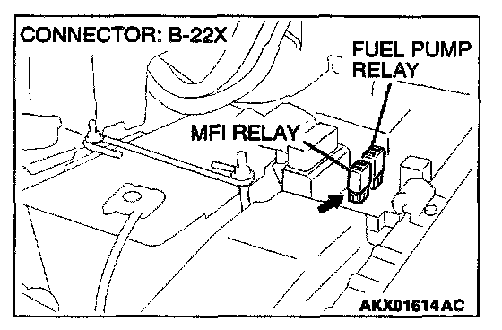
1. Remove the MFI relay.
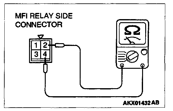
2. Check for continuity between the MFI relay terminals 2 and 4.
- There should be continuity (approximately 0.70 ohm)
3. Use jumper wires to connect MFI relay terminal 2 to the positive battery terminal and terminal 4 to the negative battery terminal.
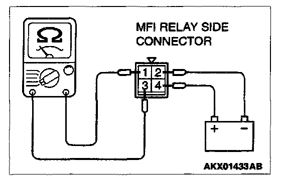
4. Check the continuity between the MFI relay terminals 1 and 3 while connecting and disconnecting the jumper wire at the negative battery terminal.
- Should be less than 2 ohm. (Negative battery terminal connected)
- Should be open loop. (Negative battery terminal disconnected)
5. Install the MFI relay.
Q: Is the voltage normal?
YES: Go to Step 3.
NO: Replace the MFI relay. Then confirm that the malfunction symptom is eliminated.
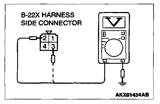
STEP 3. Check the power supply voltage at MFI relay harness side connector B-22X.
1. Disconnect the connector B-22X and measure at the harness side.
2. Measure the voltage between terminal 2, 3 and ground.
- Voltage should be battery positive voltage.
Q: Is the voltage normal?
YES: Go to Step 4.
NO: Check harness connector A-03 at intermediate connector for damage, and repair or replace as required. Refer to Harness Connector Inspection. If intermediate connector A-03 is in good condition, repair an open circuit between fusible link (6) and MFI relay connector B-22X terminal 2, 3. Then confirm that the malfunction symptom is eliminated.
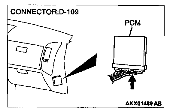
STEP 4. Check harness connector D-109 at PCM for damage.
Q: Is the harness connector in good condition?
YES: Go to Step 5.
NO: Repair or replace it. Refer to Harness Connector Inspection. Then confirm that the malfunction symptom is eliminated.
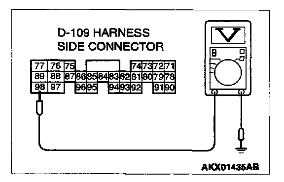
STEP 5. Check the ignition switch-IG signal voltage at PCM harness side connector D-109.
1. Disconnect the connector D-109 and measure at the harness side.
2. Turn the ignition switch to the "ON" position.
3. Measure the voltage between terminal 98 and ground.
- Voltage should be battery positive voltage.
4. Turn the ignition switch to the "LOCK" (OFF) position.
Q: Is the voltage normal?
YES: Go to Step 6.
NO: Check harness connector E-111 at intermediate connector for damage, and repair or replace as required. Refer to Harness Connector Inspection. If intermediate connector E-111 is in good condition, repair it because of open circuit between ignition switch connector D-204 terminal 2 and PCM connector D-109 terminal 98. Then confirm that the malfunction symptom is eliminated.

STEP 6. Check the backup power supply voltage at PCM harness side connector D-108.
1. Disconnect the connector D-108 and measure at the harness side.
2. Measure the voltage between terminal 66 and ground.
- Voltage should be battery positive voltage.
Q: Is the voltage normal?
YES: Go to Step 7.
NO: Check harness connector E-111, D-02, D-28 at intermediate connector for damage, and repair or replace as required. Refer to Harness Connector Inspection. If intermediate connector E-111, D-02, D-28 are in good condition, repair an open circuit between fusible link (2) and PCM connector D-108 terminal 66. Then confirm that the malfunction symptom is eliminated.
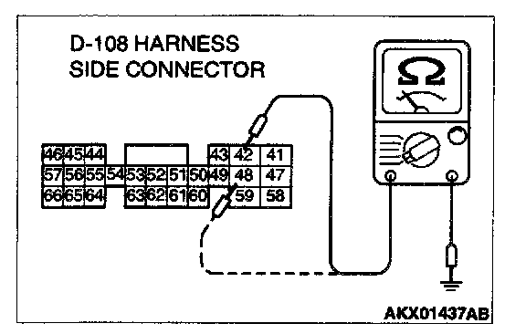
STEP 7. Check the continuity at PCM harness side connector D-108.
1. Disconnect the connector D-108 and measure at the harness side.
2. Check for the continuity between terminal 42, 48 and ground.
- Should be less than 2 ohm.
Q: Is the continuity normal?
YES: Go to Step 8.
NO: Check harness connector D-14 at intermediate connector for damage, and repair or replace as required. Refer to Harness Connector Inspection. If intermediate connector D-14 is in good condition, repair an open circuit or harness damage between PCM connector D-108 terminal 42, 48 and ground. Then confirm that the malfunction symptom is eliminated.
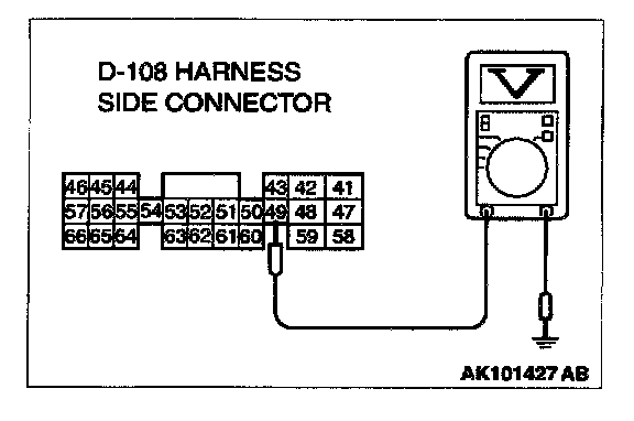
STEP 8. Check the power supply voltage at PCM harness side connector D-108.
1. Disconnect the connector D-108 and measure at the harness side.
2. Measure the voltage between terminal 49 and ground.
- Voltage should be battery positive voltage.
Q: Is the voltage normal?
YES: Go to Step 9.
NO: Repair an open circuit between MFI relay connector B-22X terminal 4 and PCM connector D-108 terminal 49. Then confirm that the malfunction symptom is eliminated.
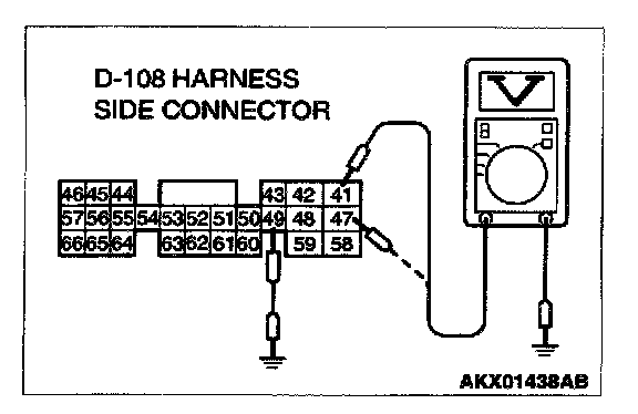
STEP 9. Check the power supply voltage at PCM harness side connector D-108.
1. Disconnect the connector D-108 and measure at the harness side.
2. Using a jumper wire, connect terminal 49 to ground.
3. Measure the voltage between terminal 41, 47 and ground.
- Voltage should be battery positive voltage.
Q: Is the voltage normal?
YES: Replace the PCM. Then confirm that the malfunction symptom is eliminated.
NO: Check harness connector D-116 at intermediate connector for damage, and repair or replace as required. Refer to Harness Connector Inspection. If intermediate connector D-116 is in good condition, repair an open circuit between MFI relay connector B-22X terminal 1 and PCM connector D-108 terminal 41, 47. Then confirm that the malfunction symptom is eliminated.