Inspection Procedure 31
Ignition Circuit:
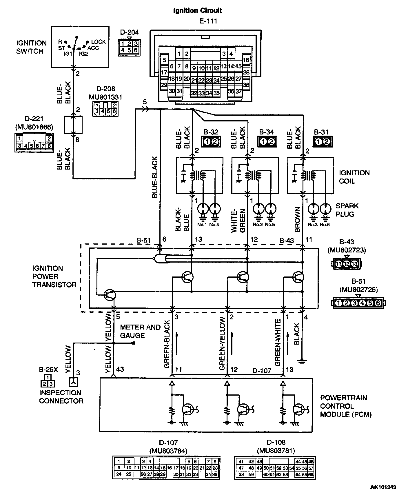
Connectors:
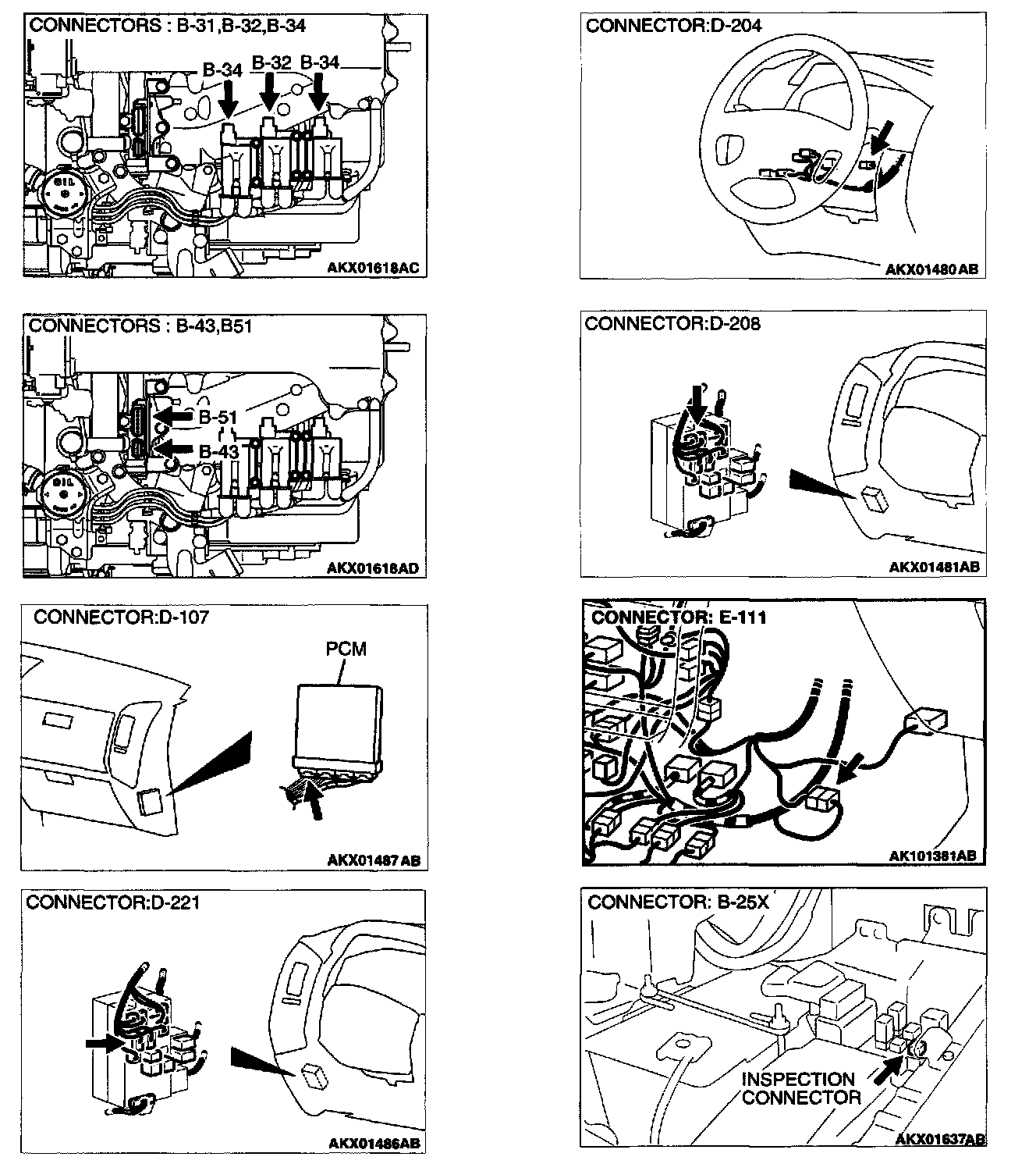
COMMENT
- The battery positive voltage is applied on the ignition coil by the ignition switch-IG.
- When the PCM turns the power transistor in the PCM "OFF", battery positive voltage is applied on the ignition power transistor (terminals 3), and the ignition power transistor turns "ON".
- When the ignition power transistor turns "ON" the ignition coil's primary circuit is grounded by the ignition power transistor terminal 4. Then the primary current flows to the ignition coil.
TROUBLESHOOTING HINTS (The most likely causes for this case:)
- Malfunction of the ignition coil.
- Malfunction of the ignition power transistor.
- Improper connector contact, open circuit or short- circuited harness wire.
- Malfunction of the PCM.
DIAGNOSIS
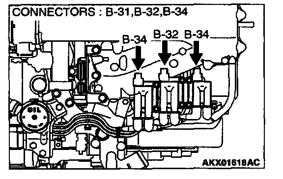
STEP 1. Check harness connectors B-31, B-32, B-44 at ignition coil for damage.
Q: Is the harness connector in good condition?
YES: Go to Step 2.
NO: Repair or replace it. Refer to Harness Connector Inspection. Then confirm that the malfunction symptom is eliminated.
STEP 2. Check the ignition coil.
Refer to Ignition System - Ignition Coil Check.
Q: Are there any abnormalities?
YES: Go to Step 3.
NO: Replace the ignition coil. Then confirm that the malfunction symptom is eliminated.
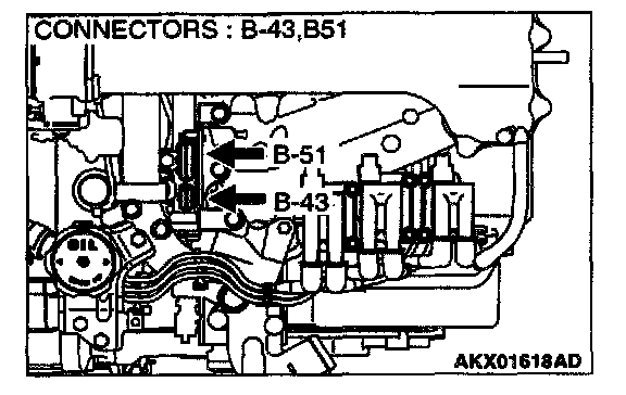
STEP 3. Check harness connectors B-43, B-51 at ignition power transistor for damage.
Q: Is the harness connector in good condition?
YES: Go to Step 4.
NO: Refer to Harness Connector Inspection. Then confirm that the malfunction symptom is eliminated.
STEP 4. Check the ignition power transistor.
Refer to Ignition System - Ignition Coil Power Transistor Continuity Check.
Q: Are there any abnormalities?
YES: Go to Step 5.
NO: Replace the ignition power transistor. Then confirm that the malfunction symptom is eliminated.
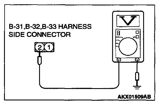
STEP 5. Check the power supply voltage at ignition coil connectors B-31, B-32, B-34.
1. Disconnect the connectors B-31, B-32, B-34 and measure at the harness side.
2. Turn the ignition switch to the "ON" position.
3. Measure the voltage between terminal 2 and ground.
- Voltage should be battery positive voltage.
4. Turn the ignition switch to the "LOCK" (OFF) position.
Q: Is the voltage normal?
YES: Go to Step 6.
NO: Check harness connector D-208, D-221 and E-111 at intermediate connector for damage, and repair or replace as required. Refer to Harness Connector Inspection. If intermediate connector D-208, D-221 and E-111 is in good condition, repair an open circuit between ignition switch connector D-204 terminal 2 and ignition coil connectors B-31, B-32, B- 34 terminal 2. Then confirm that the malfunction symptom is eliminated.
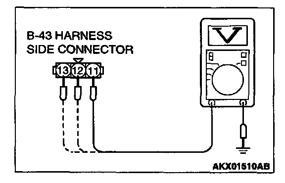
STEP 6. Check the power supply voltage at ignition power transistor connector B-43.
1. Disconnect the connector B-43 and measure at the harness side.
2. Turn the ignition switch to the "ON" position.
3. Measure the voltage between terminal 11,12,13 and ground.
- Voltage should be battery positive voltage.
4. Turn the ignition switch to the "LOCK" (OFF) position.
Q: Is the voltage normal?
YES: Go to Step 7.
NO: Repair it because of open circuit between ignition coil connectors B-31, B-32, B-34 terminal 1 and ignition power transistor connector B-43 terminals 11,12,13. Then confirm that the malfunction symptom is eliminated.
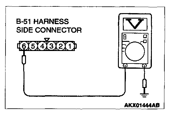
STEP 7. Check the power supply voltage at ignition power transistor connector B-51.
1. Disconnect the connector B-51 and measure at the harness side.
2. Turn the ignition switch to the "ON" position.
3. Measure the voltage between terminal 6 and ground.
- Voltage should be battery positive voltage.
4. Turn the ignition switch to the "LOCK" (OFF) position.
Q: Is the voltage normal?
YES: Go to Step 8.
NO: Check harness connector D-208, D-221 and E-111 at intermediate connector for damage, and repair or replace as required. Refer to Harness Connector Inspection. If intermediate connector D-208, D-221 and E-111 is in good condition, repair an open circuit between ignition switch connector D-204 terminal 2 and ignition power transistor connector B-51 terminal 6. Then confirm that the malfunction symptom is eliminated.
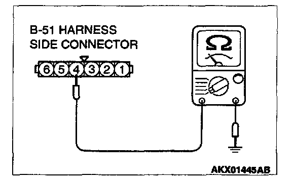
STEP 8. Check the continuity at ignition power transistor harness side connector B-51.
1. Disconnect the connector B-51 and measure at the harness side.
2. Check for the continuity between terminal 4 and ground.
- Should be less than 2 ohm.
Q: Is the continuity normal?
YES: Go to Step 9.
NO: Repair it because of open circuit or harness damage between ignition power transistor connector B-51 terminal 4 and ground. Then confirm that the malfunction symptom is eliminated.
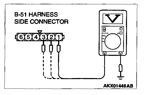
STEP 9. Check the circuit at ignition power transistor connector B-51.
1. Disconnect the connector B-51 and measure at the harness side.
2. Crank the engine.
3. Measure the voltage between terminals 1, 2, 3 and ground.
- Voltage should be between 0.5 and 4.0 volts.
4. Turn the ignition switch to the "LOCK" (OFF) position.
Q: Is the voltage normal?
YES: Refer to Chassis electrical - Combination meters assembly and vehicle speed sensor - Tachometer check.
NO: Go to Step 10.
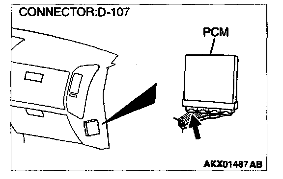
STEP 10. Check harness connector D-107 at PCM for damage.
Q: Is the harness connector in good condition?
YES: Go to Step 11
NO: Repair or replace it. Refer to Harness Connector Inspection. Then confirm that the malfunction symptom is eliminated.
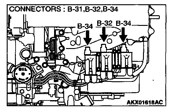
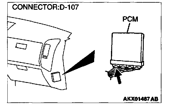
STEP 11. Check for open circuit between ignition power transistor connector B-51 terminal 1, 2, 3 and PCM connector D-107 terminal 11, 12, 13.
Q: Is the harness wire in good condition?
YES: Replace the PCM. Then confirm that the malfunction symptom is eliminated.
NO: Repair it. Then confirm that the malfunction symptom is eliminated.