System Specifications
SERVICE DATA AND SPECIFICATIONS (SDS)
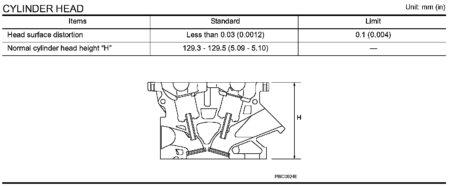
CYLINDER HEAD
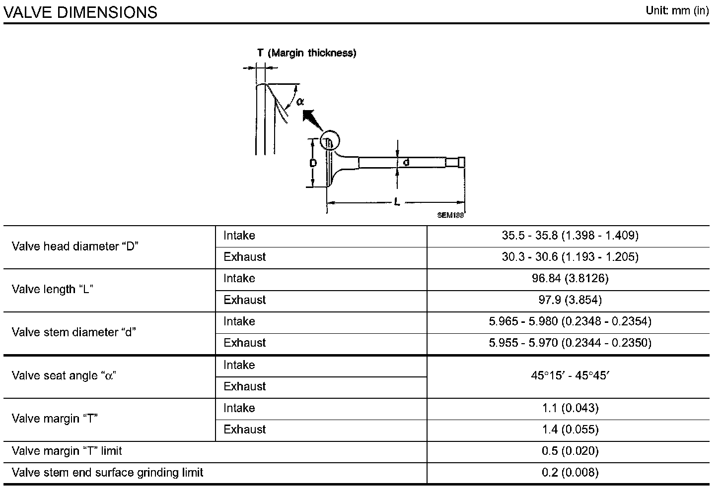
VALVE DIMENSIONS
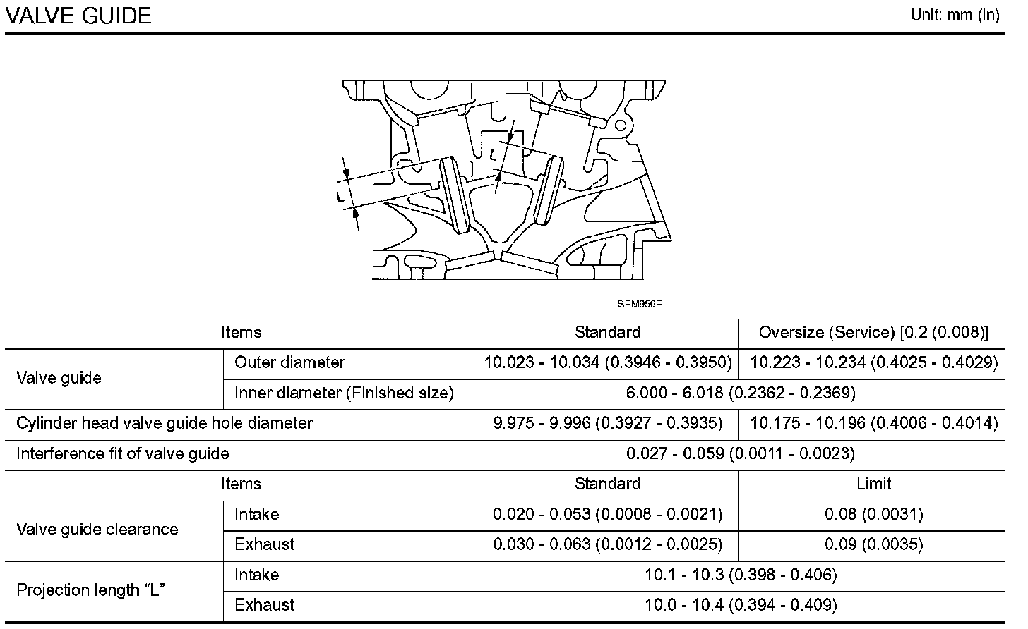
VALVE GUIDE
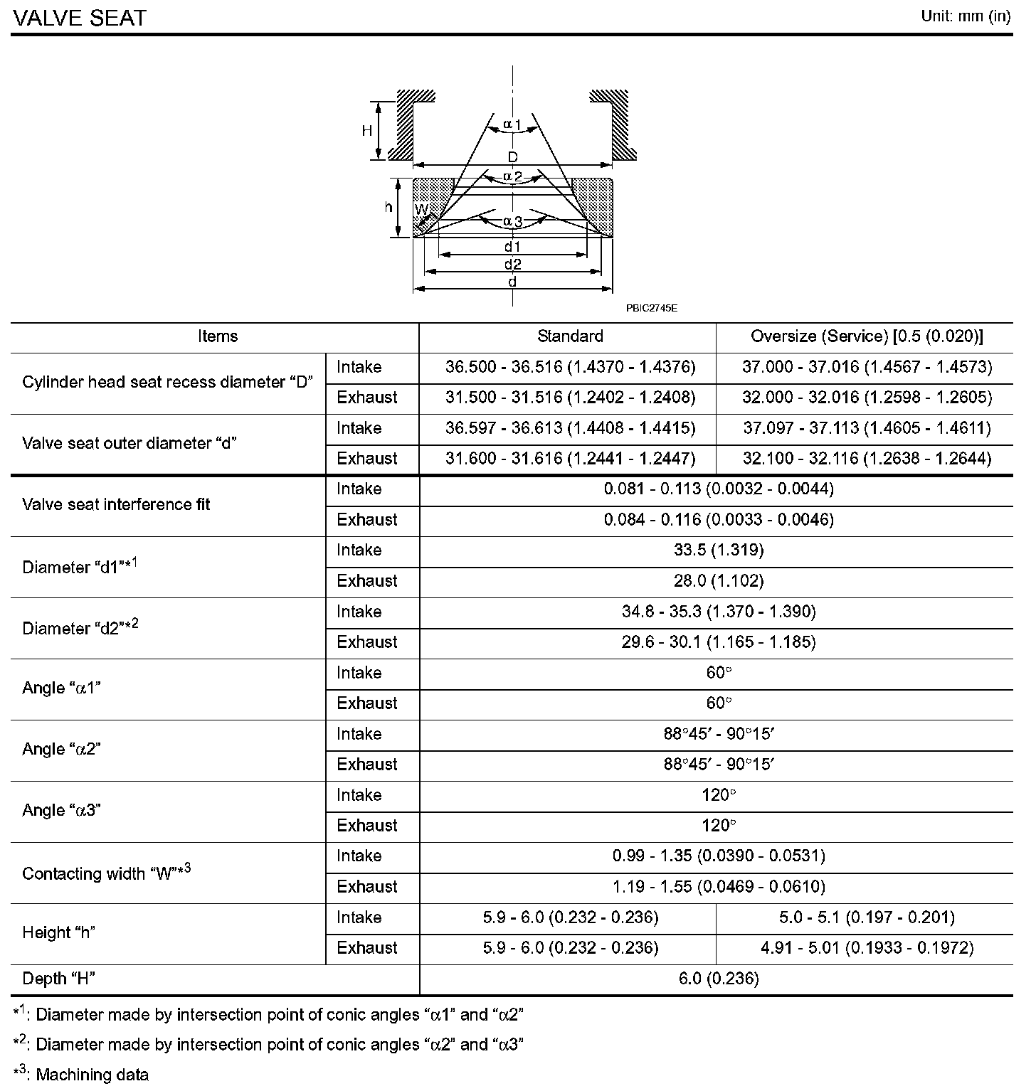
VALVE SEAT
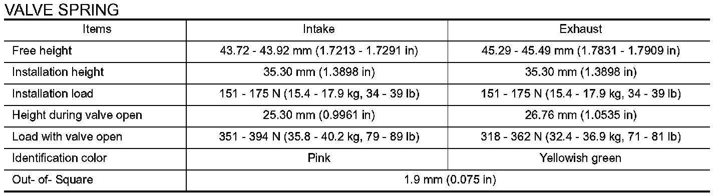
VALVE SPRING
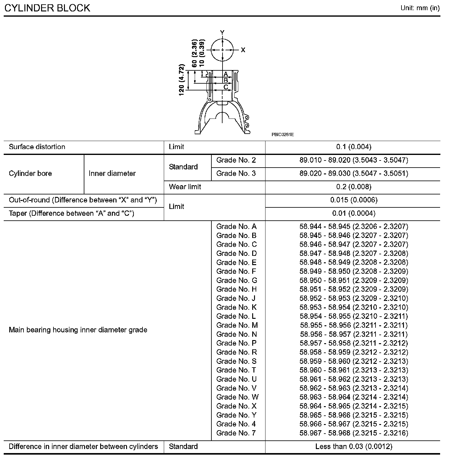
CYLINDER BLOCK
Cylinder Head
1. Install cylinder head gasket.
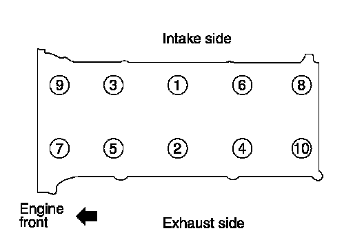
2. Tighten cylinder head bolts in numerical order as shown in the figure with the following procedure, and install cylinder head.
CAUTION:
If cylinder head bolts are reused, check their outer diameters before installation. Refer to Inspection.
a. Apply new engine oil to threads and seating surface of mounting bolts.
b. Tighten all bolts.
Torque : 50.0 N.m (5.1 kg-m, 37 ft-lb)
c. Turn all bolts 60 degrees clockwise (angle tightening).
d. Completely loosen.
Torque : 0 N.m (0 kg-m, 0 ft-lb)
CAUTION:
In this step, loosen bolts in the reverse order of that indicated in the figure.
e. Tighten all bolts.
Torque : 39.2 N.m (4.0 kg-m, 29 ft-lb)
f. Turn all bolts 75 degrees clockwise (angle tightening).
g. Turn all bolts 75 degrees clockwise again (angle tightening).
CAUTION:
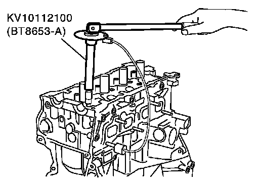
Check and confirm the tightening angle by using an angle wrench (SST) or protractor. Avoid judgment by visual inspection without the tool.
Intake Manifold
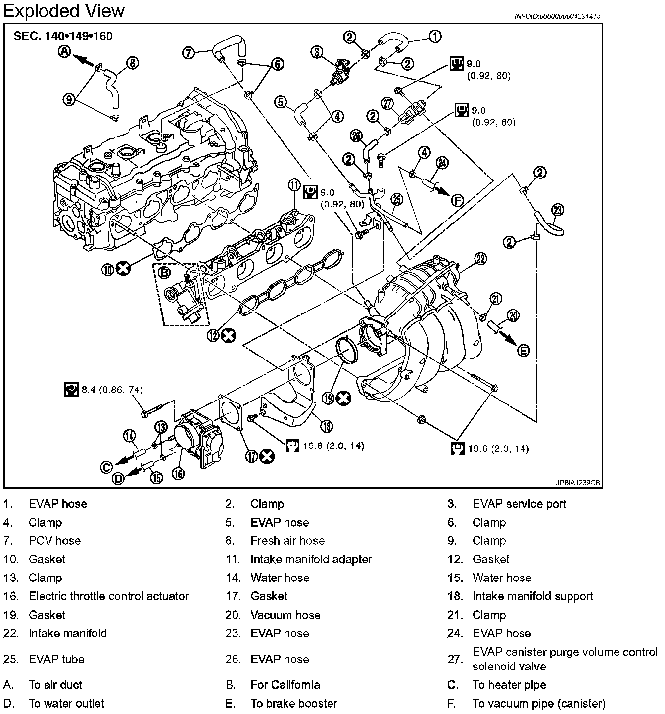
Refer to Component for symbols in the figure.
- If stud bolts were removed, install them and tighten to the specified torque below.
Torque : 9.4 N.m (0.96 kg-m, 83 in-lb)
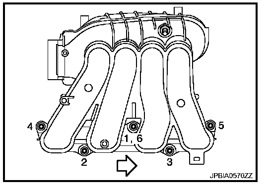
- Tighten in numerical order as shown in the figure.
White Arrow Indicates: Engine front
NOTE:
No. 6 means double tightening of bolt No. 1.
Camshaft Bearing Cap
Tighten mounting bolts of camshaft brackets in the following steps, in numerical order as shown in the figure.
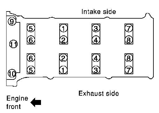
a. Tighten No. 9 to 11 in numerical order.
Torque : 2.0 N.m (0.20 kg-m, 1 ft-lb)
b. Tighten No. 1 to 8 in numerical order.
Torque : 2.0 N.m (0.20 kg-m, 1 ft-lb)
c. Tighten all bolts in numerical order.
Torque : 5.9 N.m (0.60 kg-m, 4 ft-lb)
d. Tighten all bolts in numerical order.
Torque : 10.4 N.m (1.1 kg-m, 8 ft-lb)
Camshaft Gear/Sprocket
Camshaft sprocket bolt (INT) : 103 N.m (11 kg-m, 76 ft-lb)
Camshaft sprocket bolt (EXH) : 142 N.m (14 kg-m, 105 ft-lb)
EXHAUST MANIFOLD
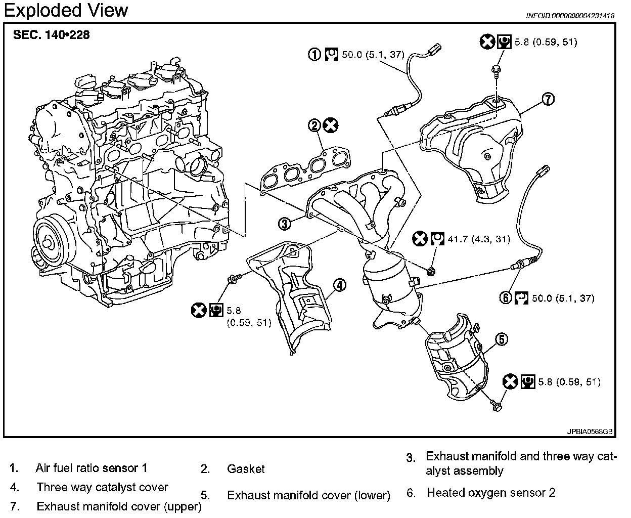
Refer to Component for symbols in the figure.
- If stud bolts were removed, install them and tighten to the specified torque below.
Torque: 14.7 N.m (1.5 kg-m, 11 ft-lb)
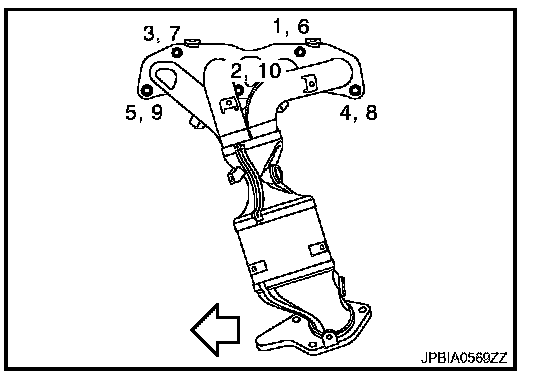
White Arrow Indicates : Engine front
- Tighten nuts in numerical order as shown in the figure.
NOTE:
No. 6 to 10 mean double tightening of bolts No. 1 and 5.