Parts Information, Service Procedure
PARTS INFORMATIONParts required to complete this modification are to be obtained from General Motors Warehousing and Distribution Division (GMWDD). To ensure that these parts will be obtained as soon as possible they should be ordered from GMWDD on a C.I.O. order with no special instruction code, but on an advise code (2).
PART NUMBER DESCRIPTION QUANTITY
10045075 Air Bleed Harness Kit 1
11508426 Washer 1
10045073 Single Port Pulsair Kit As required
It is recommended that some quantity of Air Bleed Harness Kits, Washers, and Single Port Pulsair Kits be ordered upon receipt of this bulletin to allow modification of vehicles returned unexpectedly so as to minimize owner inconvenience.
PART I - SERVICE PROCEDURE - (SINGLE PORT PULSAIR PIPE INSTALLATION KIT)
1. Open the hood. Install fender cover.
FIGURE 1 - SINGLE PORT PULSAIR PIPE ASSEMBLY P/N 10045073:
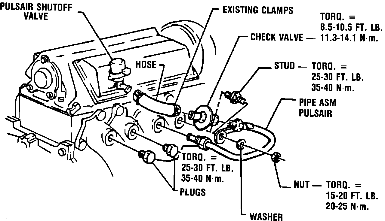
2. If the vehicle has a BLUE colored pulsair assembly, replace with a single tube kit assembly (Part Number 10045073). Follow the instruction sheet Part Number 10045074 included in the kit. (Refer to Figure 1.)
The single tube assembly should be installed by mounting the single tube fitting in the number two (#2) cylinder exhaust port. The tube bracket should be attached to the stud (plug) that will be installed in the number one (#1) cylinder exhaust port. Plugs should be installed in remaining exhaust ports #3 and #4. The supplied hose connects the single tube assembly to the pulsair solenoid housing. Proceed to PART II-SERVICE PROCEDURE for Air Bleed Valve installation.
(Vehicles with BLACK stainless steel 4-port assemblies do not require the 1-port kit. However, proceed to PART II-SERVICE PROCEDURE for Air Bleed Valve installation on these vehicles.)
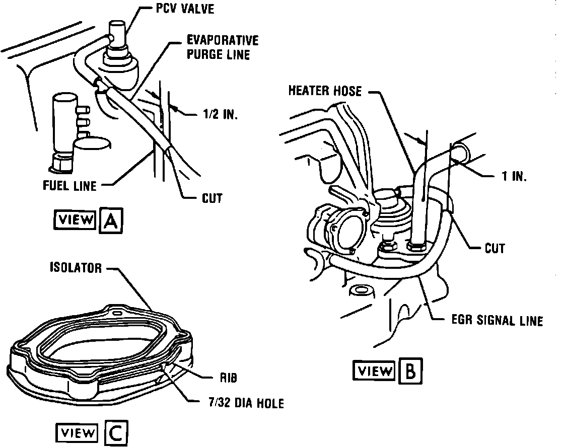
FIGURE 3 - AIR BLEED VALVE HARNESS KIT:
PART II - SERVICE PROCEDURE (AIR BLEED VALVE INSTALLATION)
All vehicles require the installation of an Air Bleed Valve Harness kit Part Number 10045075. Follow the instruction sheet Part Number 10045076 included in the kit.
1. Remove air cleaner assembly.
2. Cut evaporative purge line about 1/2 inch outboard of fuel line (see View A, Figure 3).
3. Remove rubber isolator mounted on top of carburetor. Pierce 7/32" diameter hole on rear face of isolator, directly above the "V" shaped projection (see View C, Figure 3). The top of the hole should align with the top edge of the rib on the isolator. Reinstall the isolator on the carburetor torquing screws to 2.8-4.0 N-m (25-35 in.lbs.).
4. Cut the EGR signal line about one inch outboard of the heater hose at the rear of the engine (see View B, Figure 3).
FIGURE 2 - AIR BLEED VALVE AND HARNESS ASSEMBLY:
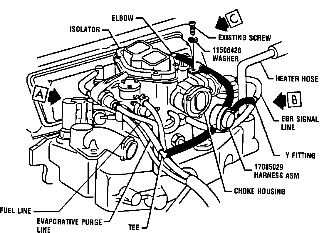
5. Assemble the air bleed valve and harness assembly to the engine (refer to Figure 2). Insert the tee fitting into the evaporative purge line. Press the 90~ elbow through the 7/32 inch hole in the carburetor isolator. Insert the "Y" plastic fitting into the EGR signal line. Assure hose from air bleed valve to isolator is dressed tight along side of vacuum break housing as shown.
6. Remove the screw which attaches the choke housing to the main body of the carburetor. Attach clip to the carburetor, using washer Part Number 11508426; torque screw to 0.6-1.7 N-m (5-14 in.lbs.).
7. Inspect the installation, making sure that there are no interference conditions with adjacent components.
8. Install air cleaner assembly and proceed to PART III - SERVICE PROCEDURE.
PART III - SERVICE PROCEDURE (TUNE-UP SPECIFICATIONS)
A. Reset Ignition Timing
1. Reset the ignition timing from 4~ BTDC to 8~ BTDC as specified on the Tune-Up label (Part Number 14100986) provided in Harness Kit Part Number 10045075. Follow the instructions for "Set Ignition Timing" in Section 6D of Service Manual.
B. Reset Idle RPM
1. Reset the idle RPM to 700 RPM in DRIVE and follow the instructions on the Tune-Up label.
C. Reset Carburetor Vacuum Break
1. Reset the carburetor vacuum break from 0.270 inches to 0.300 inches. The adjustment screw is shown in Section 6C under "Automatic Choke System" and "Vacuum Break Adjustment".
FIGURE 4 - TUNE-UP EMISSION HOSE ROUTING LABELS:
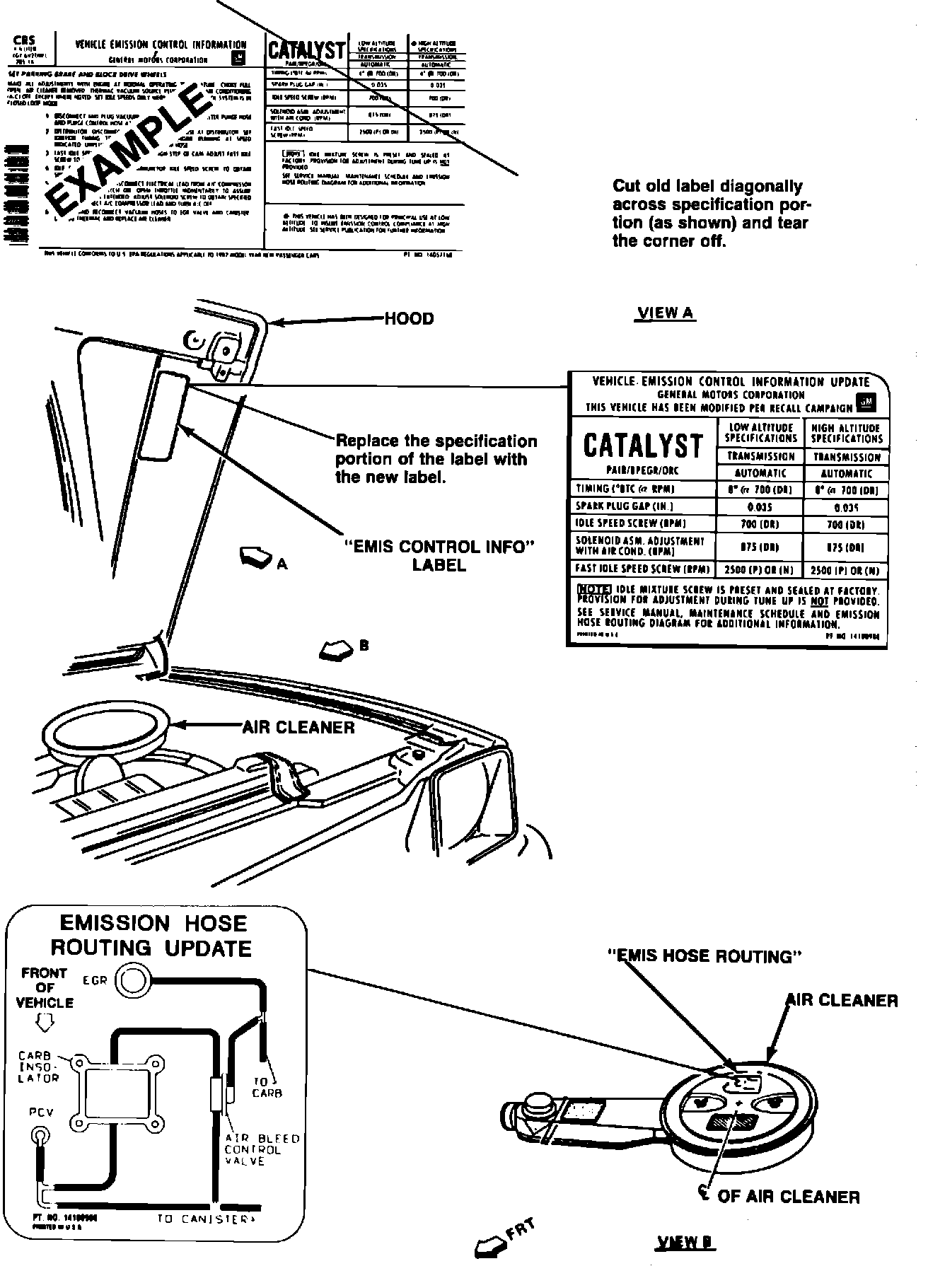
D. Install Tune-Up and Emission Hose Routing labels provided in Harness Kit Part Number 10045075. (See Figure 4.)
1. Cut the old Tune-Up label diagonally across the specification portion and remove the corner of the label. The label is located on the hood.
2. Replace the specifications portion of the Tune-Up label with the new label.
3. Add the Emission Hose Routing label to the air cleaner.
E. Install Campaign Identification Label according to following instructions. Remove fender cover and close hood.