System Diagnosis - Shift Select System
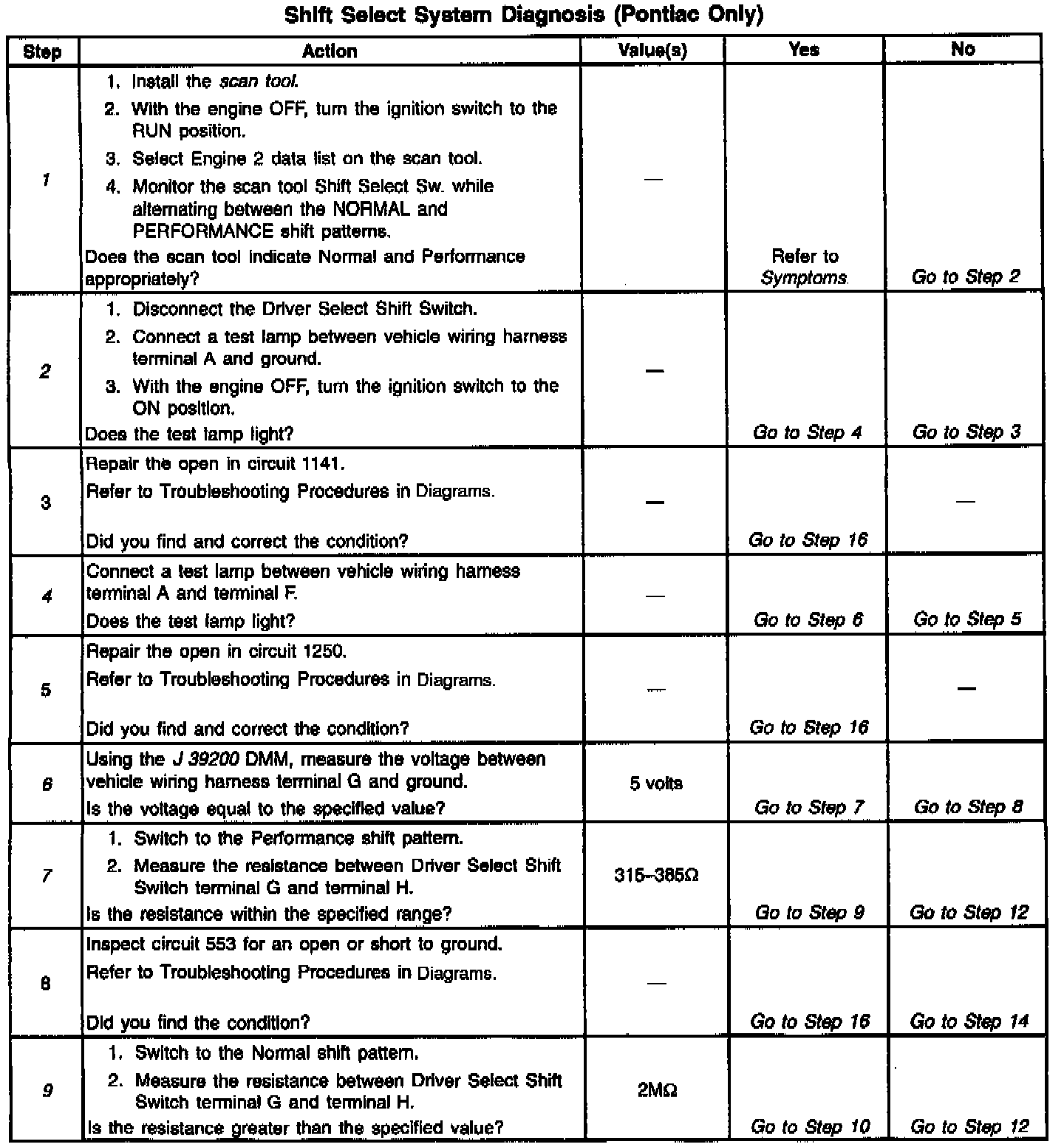
Diagnostic Chart:
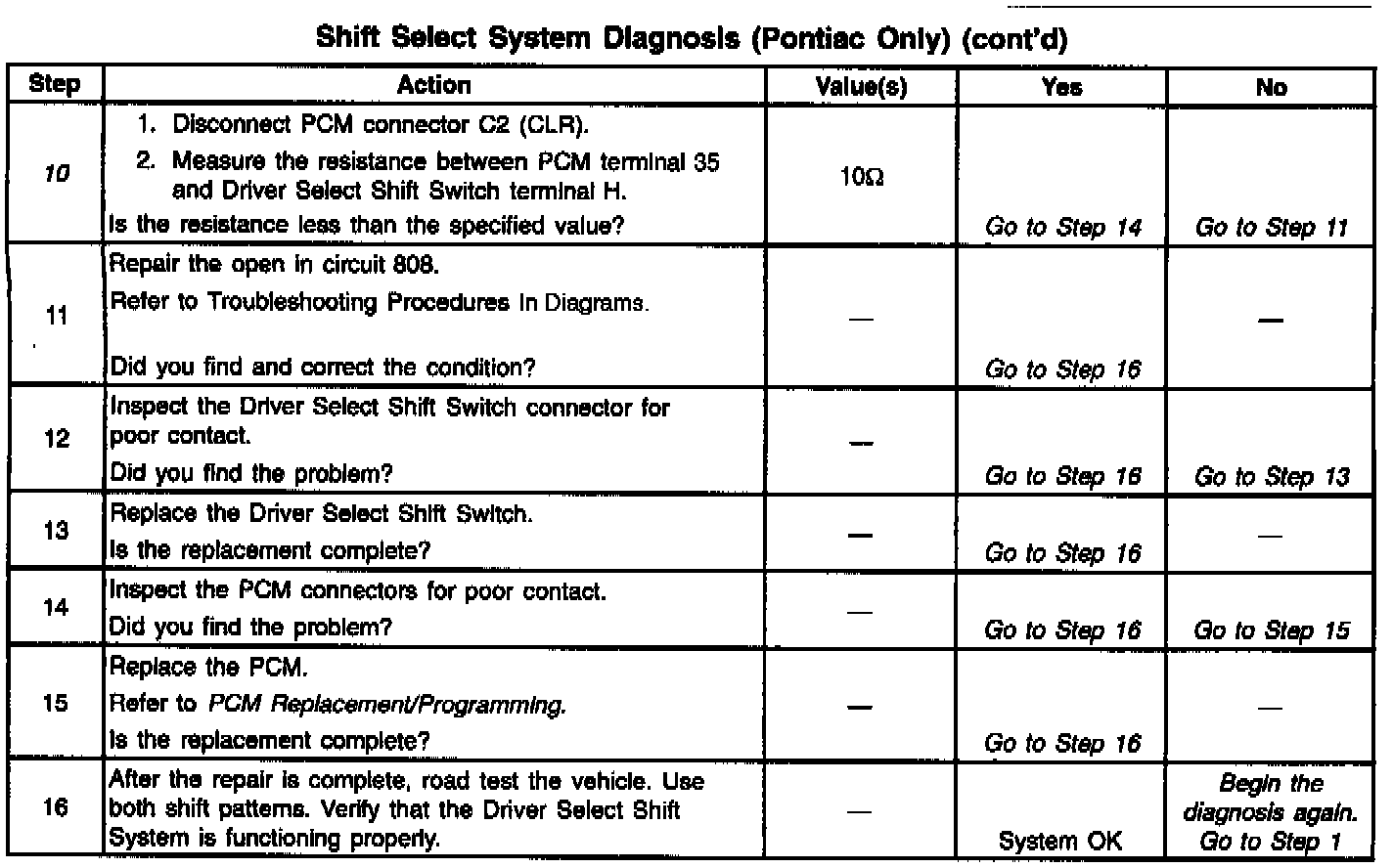
Diagnostic Chart:
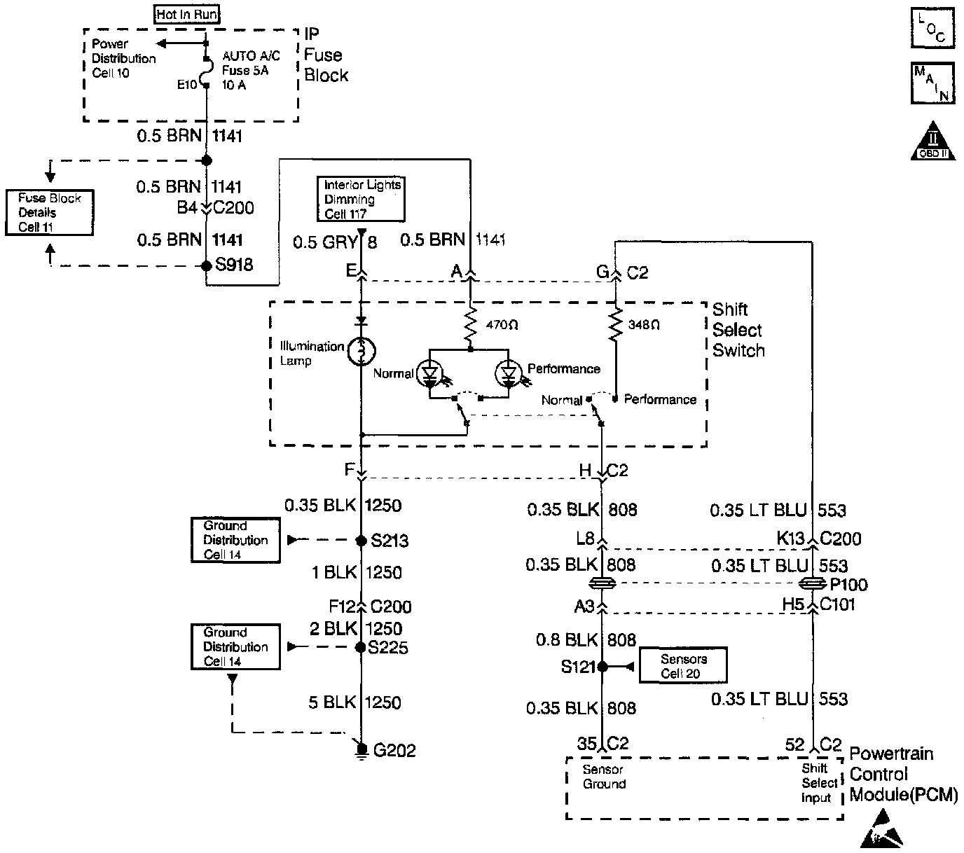
Wiring Diagram:
CIRCUIT DESCRIPTION
The Driver Select Shift System allows the driver to select one of two shift patterns, NORMAL or PERFORMANCE. Pressing the appropriate console button changes the shift pattern.
The Powertrain Control Module (PCM) provides input voltage to the Driver Select Shift Switch on circuit 553. The PCM grounds the switch on circuit 808.
The PERFORMANCE shift pattern has the following characteristics:
^ Upshifts occur at a higher engine speed.
^ Downshifts Occur at a lower percentage throttle position.
^ Engine torque output is increased in 2nd and 3rd gear.
DIAGNOSTIC AIDS
^ Inspect the I/P Fuse Block, fuse 5.
^ Inspect the wiring for poor electrical connections at the PCM. Inspect the wiring for poor electrical connections at the transmission 20-way connector. Look for the following conditions:
- A bent terminal
- A backed out terminal
- A damaged terminal
- Poor terminal tension
- A chafed wire
- A broken wire inside the insulation
^ Inspect the driver Select Shift Switch connector and the associated wiring.
^ Verify that any aftermarket electronic equipment is properly installed. Improperly installed aftermarket electronic equipment may modify the integrity of other systems.
TEST DESCRIPTION
The numbers below refer to the step numbers on the diagnostic table.
1. This step verifies that the Driver Select Shift Switch is functioning properly.
2. This step tests for system power on circuit 1141.
4. This step tests for ground on circuit 1250.
6. This step inspects the PCM input feed circuit 553.
7. This step tests the Driver Select Shift Switch internal resistor.
9. This step verities that the Driver Select Shift Switch is functioning properly.
10. This step tests the sensor ground circuit 452.