Intake Manifold Replacement
REMOVAL PROCEDURE1. Drain the cooling system.
2. Raise the vehicle and support.
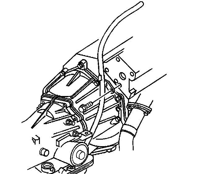
3. Remove the transmission fluid indicator tube bolt.
4. Lower the vehicle.
5. Relieve the fuel pressure. See Fuel Pressure Release.
IMPORTANT: Cap the fittings and plug the holes when separative fuel system components in order to prevent dripping of fuel and/or dirt and other contaminants from entering the fuel system.
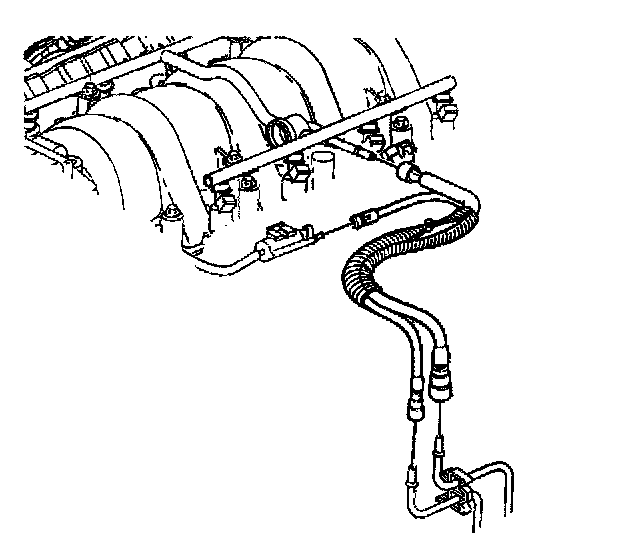
6. Disconnect the fuel lines from the fuel rail.
7. disconnect the fuel line from the fuel vapor purge valve.
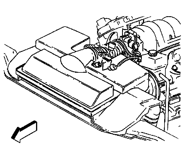
8. Disconnect the Intake Air Temperature (IAT) sensor connector at the air intake duct.
9. Disconnect the Mass Airflow (MAF) sensor connector at the air intake duct.
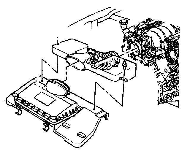
10. Remove the air intake duct from the throttle body and the air cleaner box.
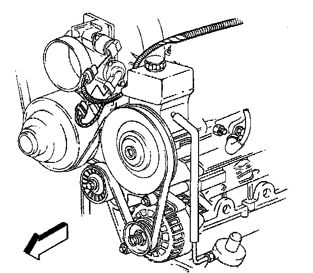
11. Disconnect the Idle Air Control (IAC) valve electrical connector from the throttle body.
12. Disconnect the Throttle Position Sensor (TPS) electrical connector from the throttle body.
13. Remove the accessory drive belt.
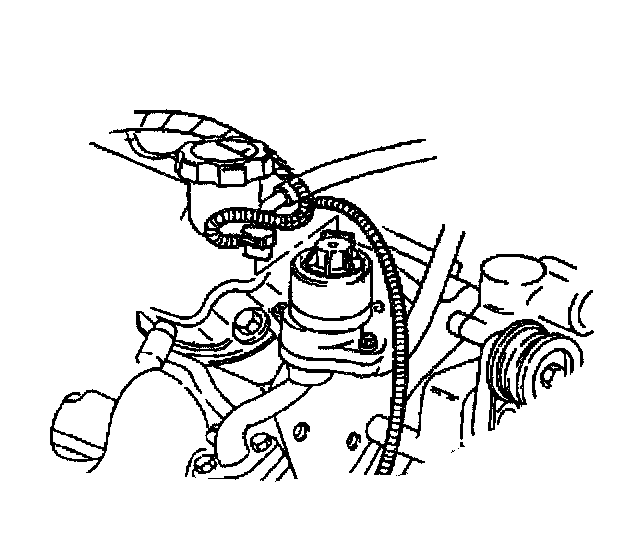
14. Disconnect the Exhaust Gas Recirculation (EGR) solenoid electrical connector.
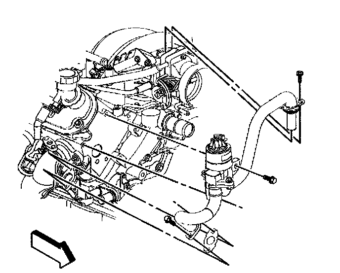
15. Remove the EGR valve pipe and solenoid,
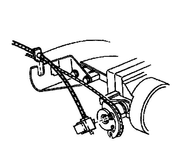
16. Unsnap the cruise control cable from the throttle lever, if equipped.
^ Push the cruise cable connector forward to unsnap.
^ Unsnap the cable from the engine bracket.
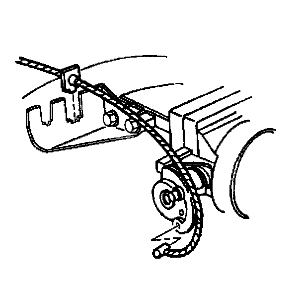
17. Remove the accelerator cable from the throttler lever.
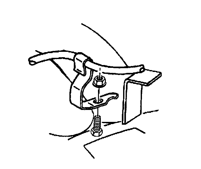
18. Remove the accelerator control cable and cruise control servo bracket.
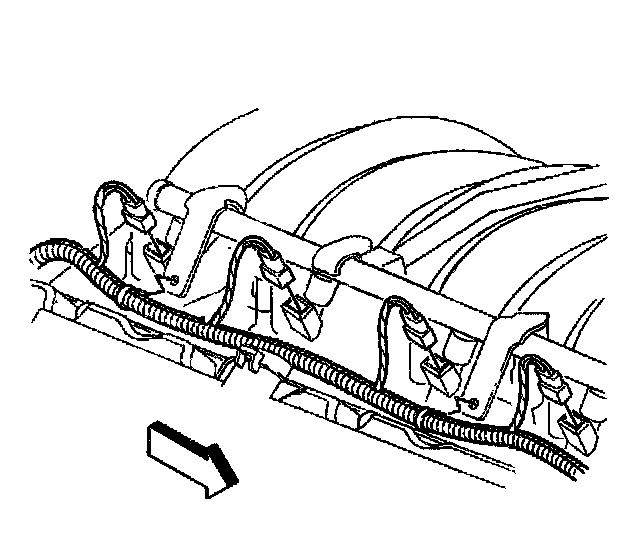
19. Disconnect the right side fuel injector connectors.
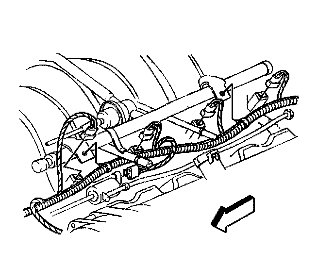
20. Disconnect the left side fuel injector connectors.
21. Remove the fuel rail.
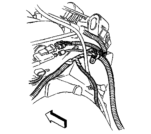
22. Disconnect the Manifold Absolute Pressure (MAP) sensor electrical connector.
23. Disconnect the vacuum hose from the vacuum port on the MAP sensor housing.
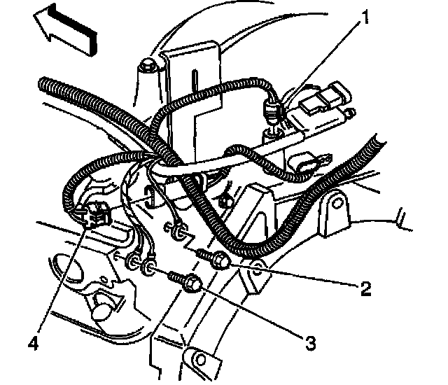
24. Disconnect the knock sensor connector (4).
25. Disconnect all the remaining electrical connections from the intake manifold.
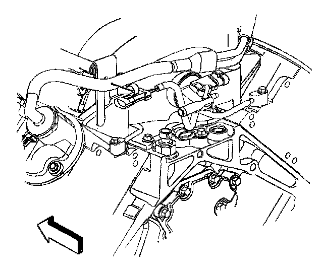
26. Remove the knock sensor jumper wire from the PCV hose.
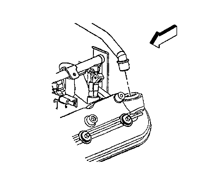
27. Remove the PCV valve pipe from the PCV valve.
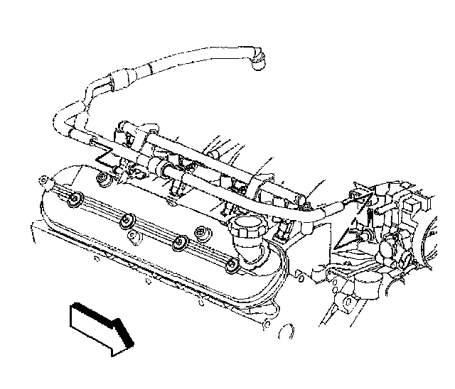
28. Remove the PCV valve pipe from the rocker cover.
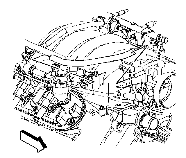
29. Remove the fresh air hose from the throttle body and coil assembly.
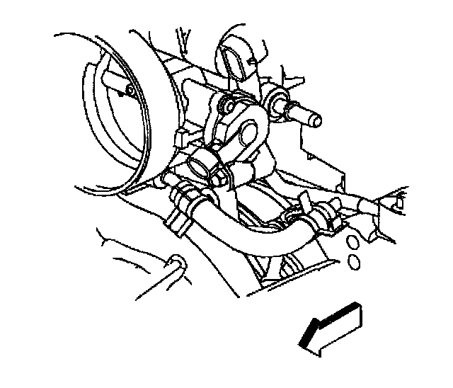
30. Remove the engine coolant air bleed hose from the throttle body.
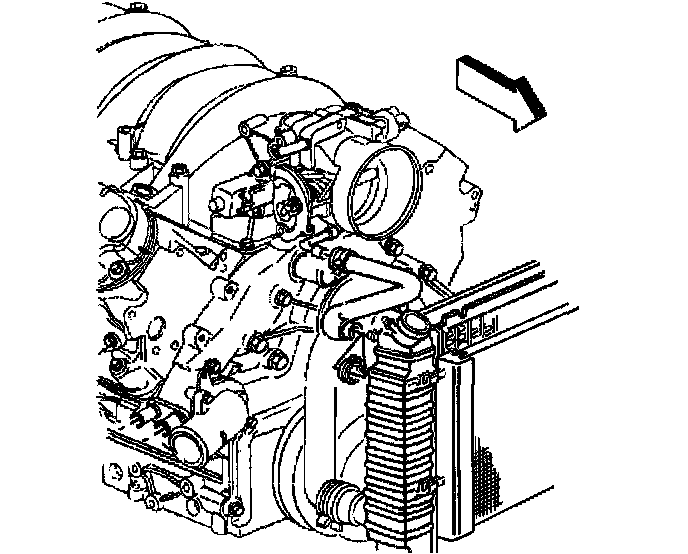
31. Remove the throttle body heater outlet hose from the throttle body.
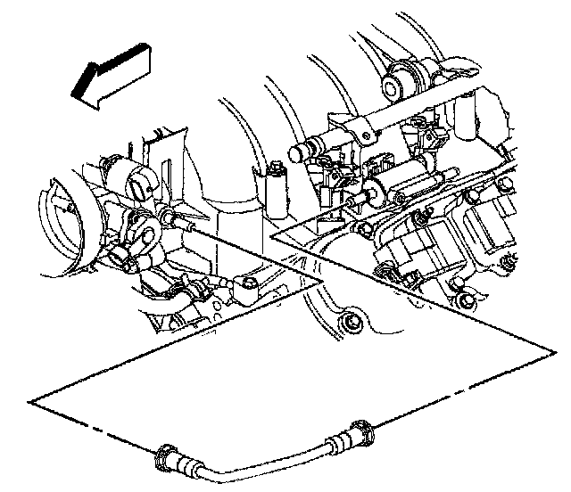
32. Remove the EVAP canister purge tube.
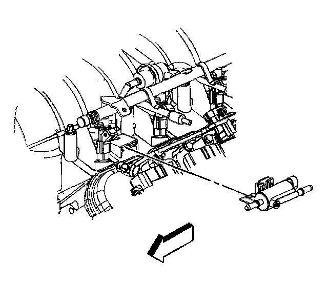
33. Remove the canister purge valve and bracket.
34. Remove the intake manifold.
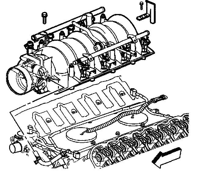
35. Remove the fuel rail stop bracket from the intake manifold.
INSTALLATION PROCEDURE
1. Install the intake manifold. Refer to "Intake Manifold Replacement" in "Unit Repair of Engine.
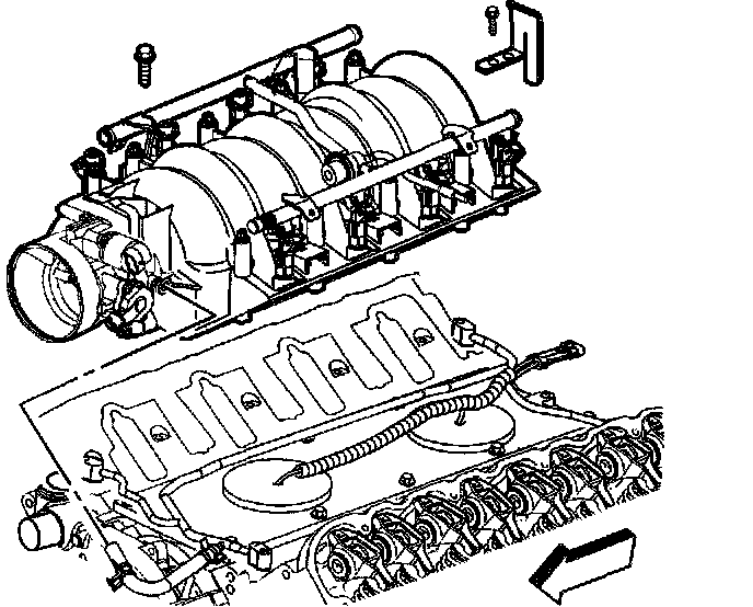
2. Install the fuel rail stop bracket to the intake manifold.
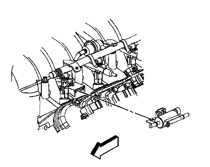
3. Install the canister purge valve and bracket.
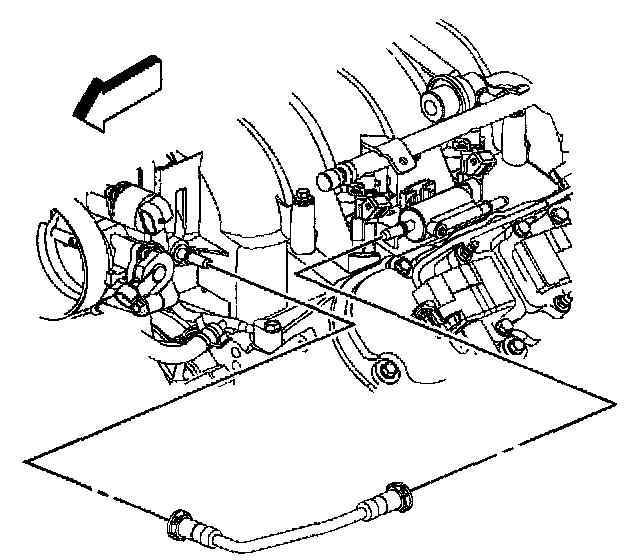
4. Install the EVAP canister purge tube.
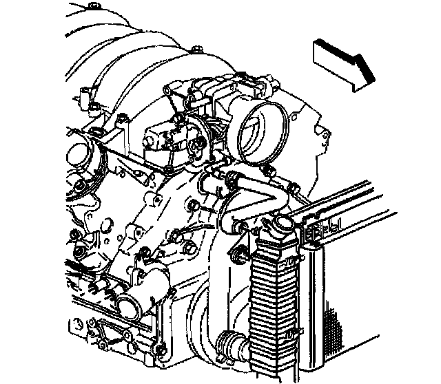
5. Install the throttle body heater outlet hose to the throttle body.
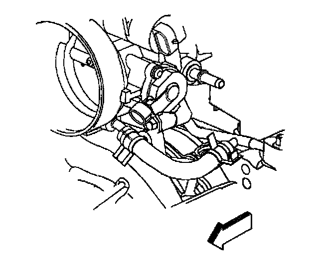
6. Install the engine coolant air bleed hose to the throttle body.
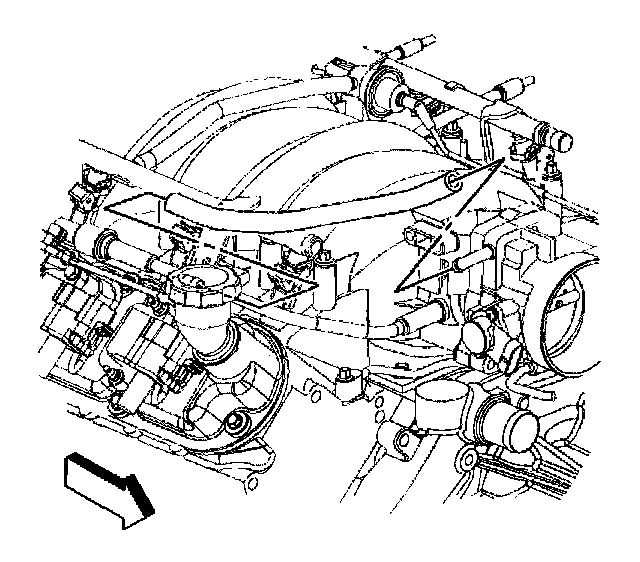
7. Install the fresh air hose to the throttle body and coil assembly.
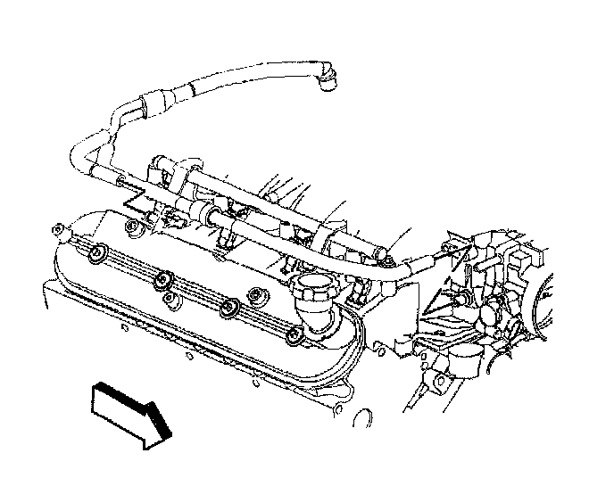
8. Connect the PCV valve pipe to the rocker cover.
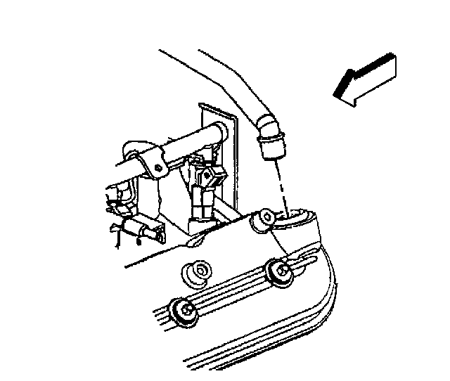
9. Connect the PCV valve pipe to the PCV valve.
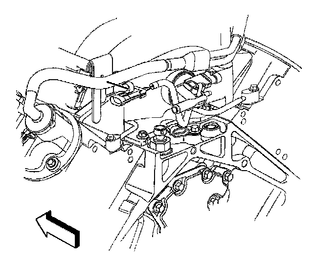
10. Connect the knock sensor jumper wire to the PCV valve hose.
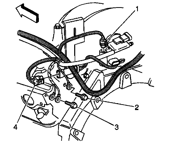
11. Connect the knock sensor connector (4).
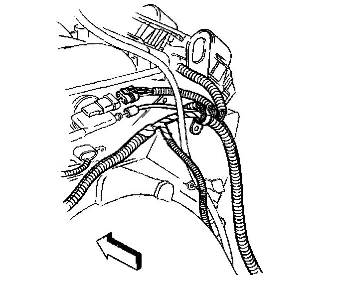
12. Connect the MAP sensor connector.
13. Connect the vacuum hose.
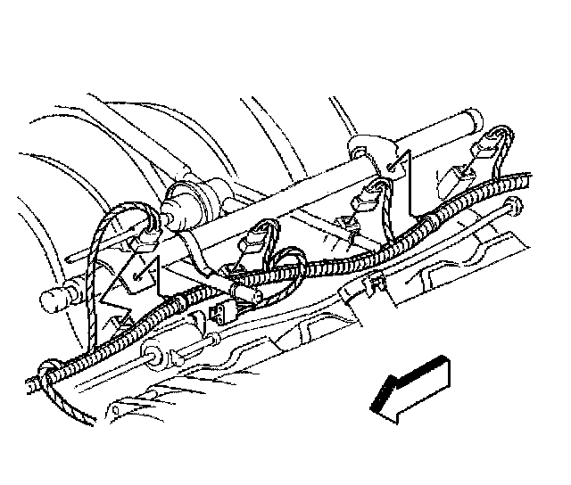
14. Connect the left side fuel injector connectors.
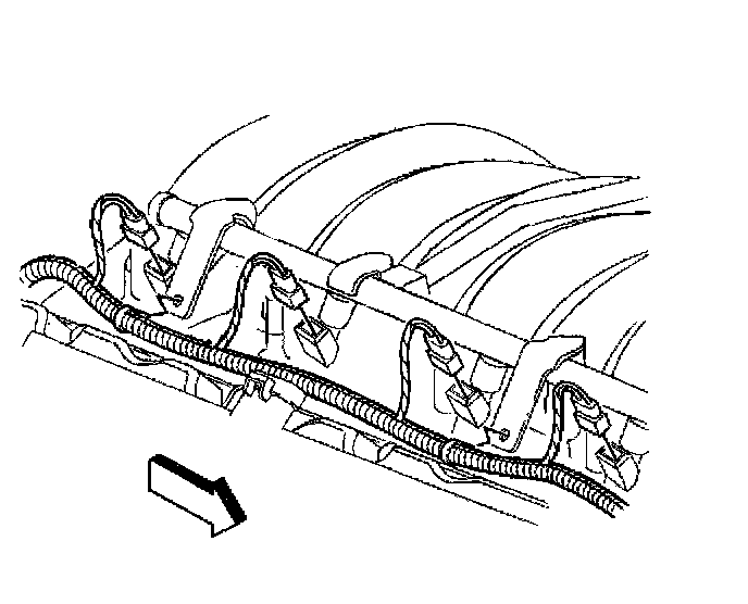
15. Connect the right side fuel injector connectors.
16. Connect all remaining electrical connectors to the intake manifold.
NOTICE: Refer to Fastener Notice in Service Precautions.
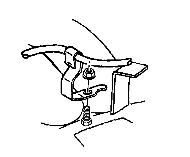
17. Install the accelerator control cable and cruise control servo bracket.
^ Tighten the accelerator control cable and cruise control servo bracket nut to 10 Nm (89 inch lbs.).
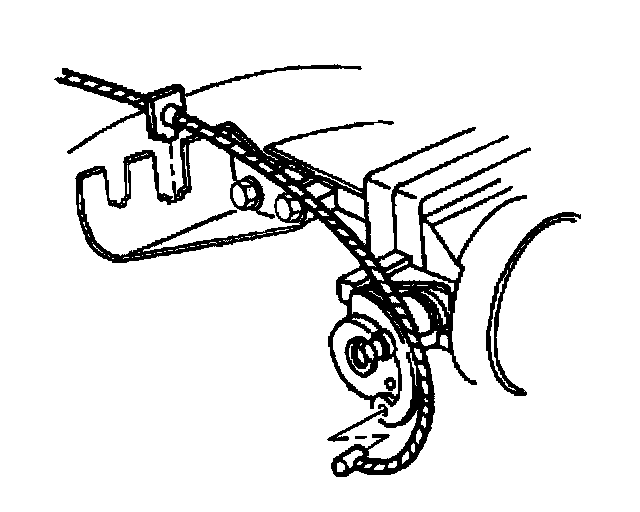
18. Install the accelerator cable to the throttle lever.
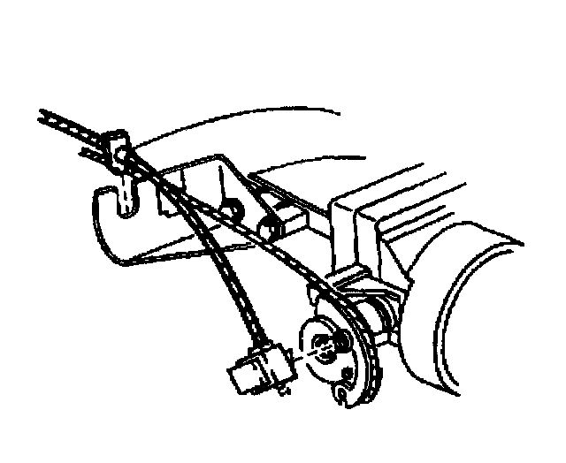
19. Install the cruise control cable to the throttle lever, if equipped.
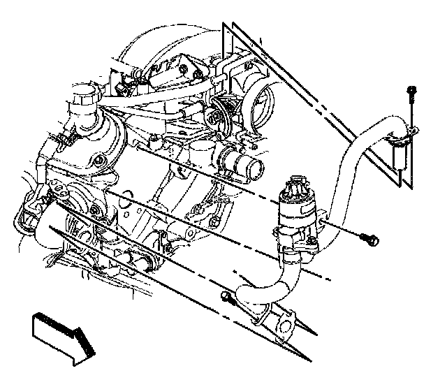
20. Install the EGR valve pipe.
^ Tighten the EGR valve pipe to exhaust manifold bolts to 25 Nm (118 ft. lbs.).
^ Tighten the EGR valve pipe to cylinder head bolt to 50 Nm (37 ft. lbs.).
^ Tighten the EGR valve pipe to intake manifold bolt to 12 Nm (106 inch lbs.).
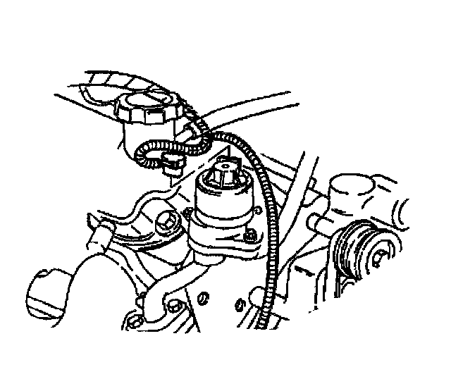
21. Connect the EGR valve connector.
22. Install the accessory drive belt.
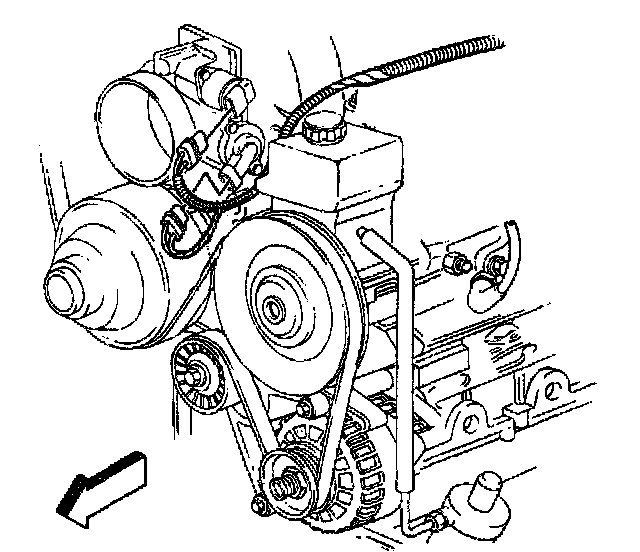
23. Connect the TIPS sensor connector to the throttle body.
24. Connect the IAC sensor connector to the throttle body.
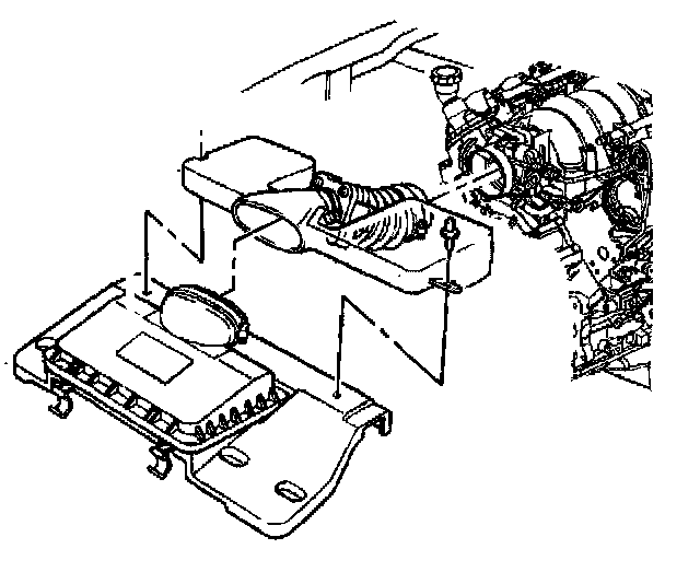
25. Install the air intake duct.
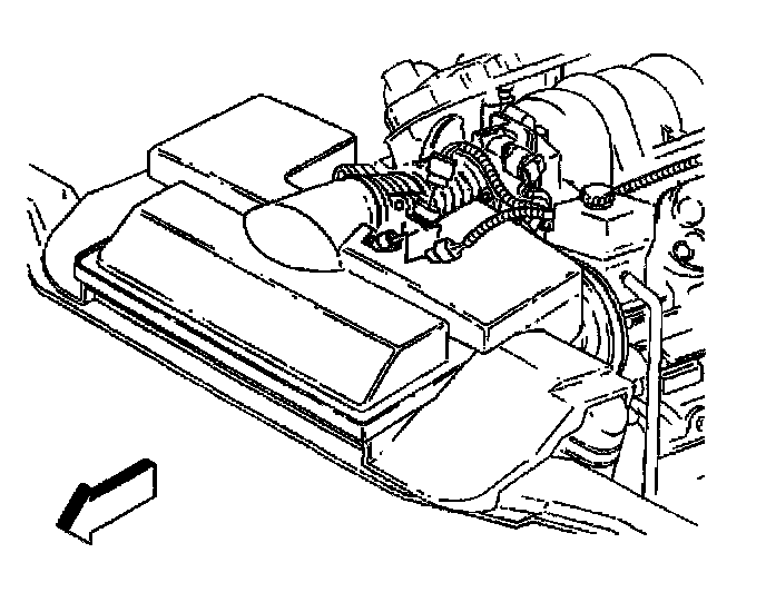
26. Connect the MAF sensor connector at the intake duct.
27. Connect the IAT sensor connector at the intake duct.
28. Remove the fuel rail.
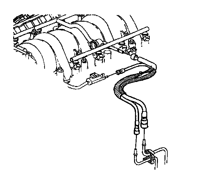
29. Connect the fuel lines to the fuel rail.
30. Connect the fuel line to the fuel vapor purge valve.
31. Raise and suitably support the vehicle.
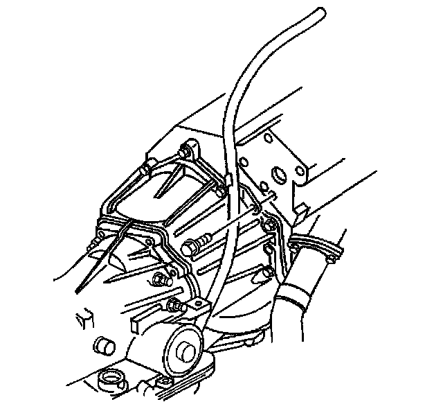
32. Install the transmission fluid indicator bolt.
^ Tighten the transmission fluid indicator tube bolt to 50 Nm (37 ft. lbs.).
33. Fill the cooling system.