Air Outlet Replacement - Defroster
AIR OUTLET REPLACEMENT - DEFROSTERREMOVAL PROCEDURE
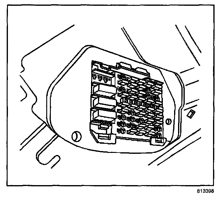
1. Disconnect the battery negative cable.
2. Remove the instrument panel (IP) trim pad.
3. Remove the passenger side SIR inflator module.
4. Remove the air distribution ducts.
5. Unclip the fuse block and position aside.
6. Remove the two screws that hold the wire harness connector to the cross car beam under the fuse box.
7. Remove the brake pedal.
8. Remove the bolts for the steering column support bracket and remove the bracket.
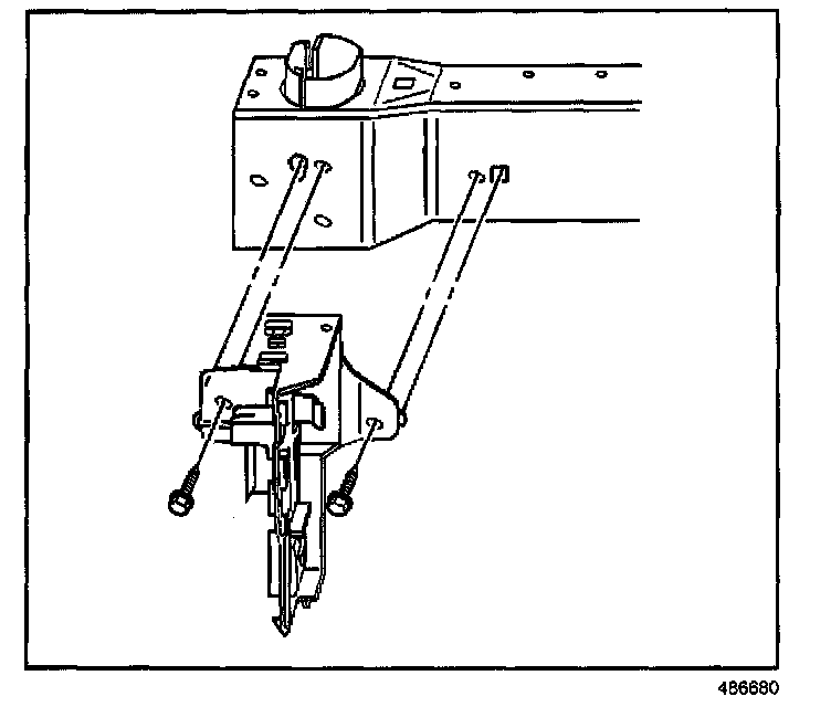
9. Remove the retaining bolts and position the BCM bracket aside.
10. Release the wiring harness retaining clips from the cross vehicle beam and position the IP wiring harness out of the way.
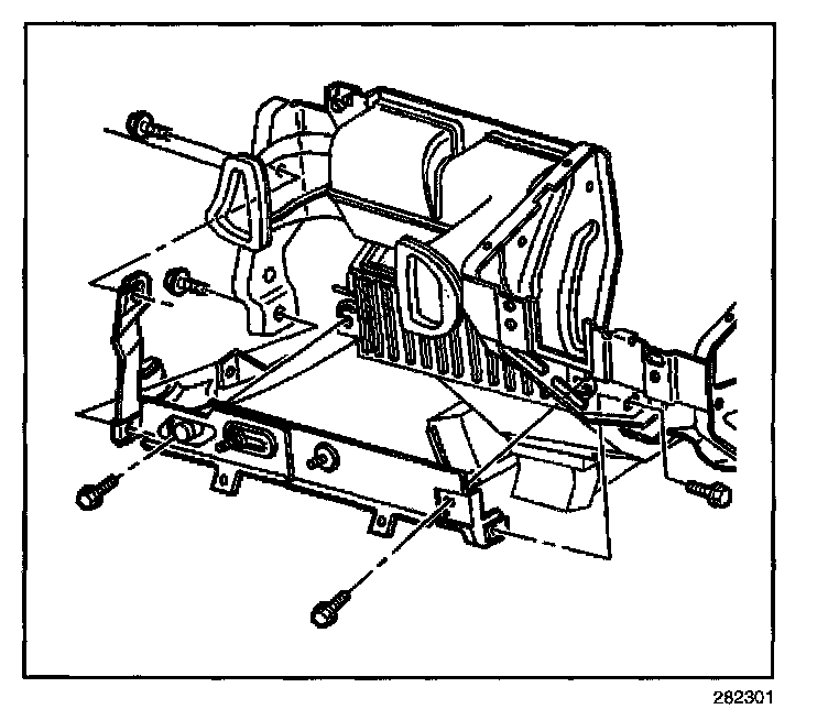
11. Remove the retaining bolts from the center support bracket of the HVAC module.
12. Remove the center support bracket of the HVAC module.
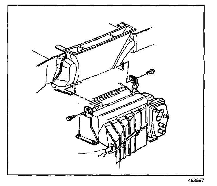
13. Remove the retaining bolts from the upper support brackets of the HVAC module.
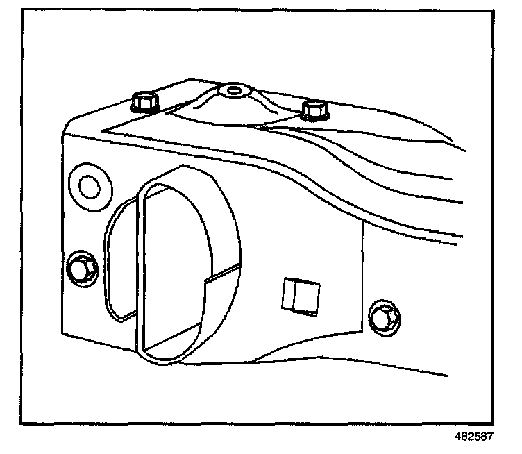
14. Remove the bolts which secure the left cross vehicle beam to the hinge pillar.
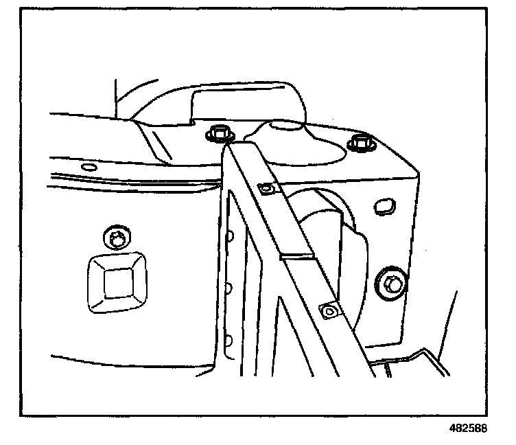
15. Remove the bolts which secure the right cross vehicle beam to the hinge pillar.
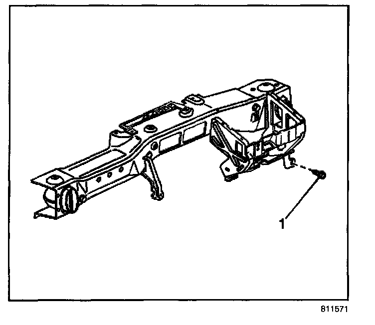
16. Remove the bolt (1) from the cross vehicle beam.
17. Remove the cross vehicle beam from the vehicle.
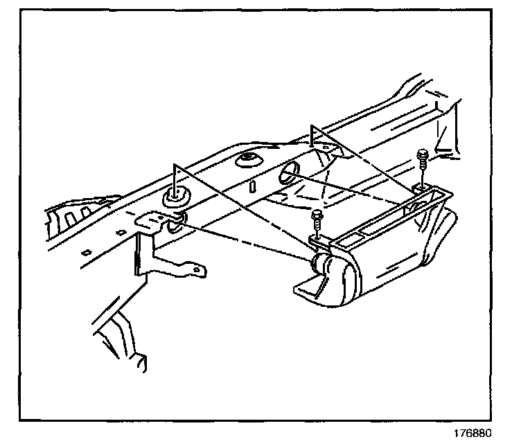
18. Remove the screws and the defroster air distribution duct.
INSTALLATION PROCEDURE
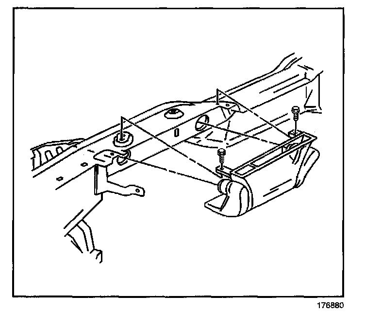
1. Install the defroster air distribution duct.
NOTE: Refer to Fastener Notice in Service Precautions.
2. Install the mounting screws.
Tighten
Tighten the screws to 1.5 N.m (13 lb in).
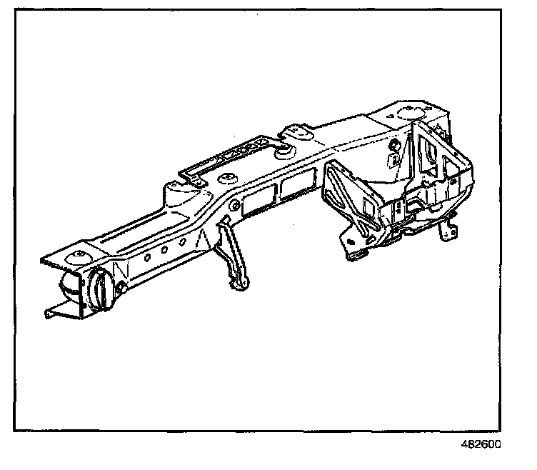
3. Install the cross vehicle beam to the vehicle.
IMPORTANT: Do NOT tighten the bolts at this time.
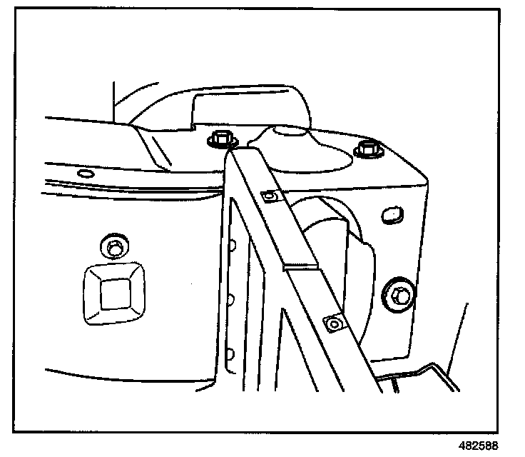
4. Install the bolts which secure the right cross vehicle beam to the hinge pillar.
NOTE: Refer to Fastener Notice in Service Precautions.
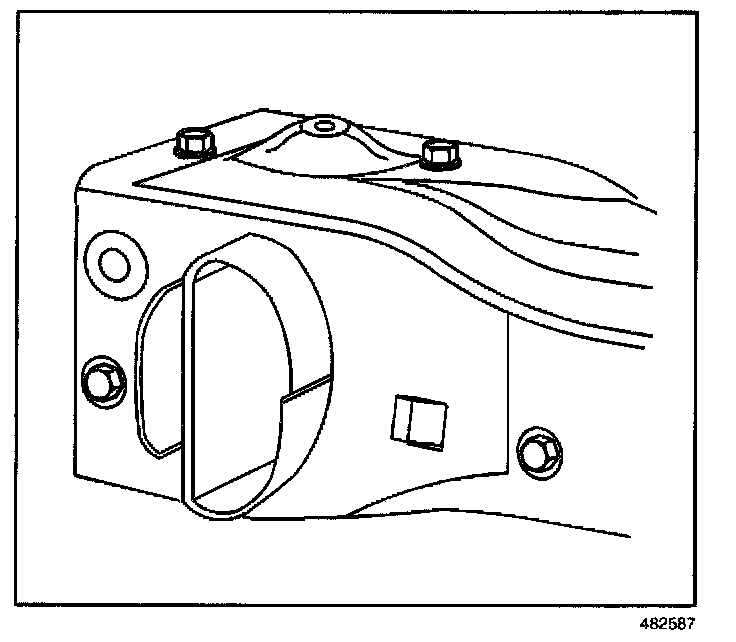
5. Install the bolts which secure the left cross vehicle beam to the hinge pillar.
Tighten
Tighten the bolts to 20 N.m (15 lb ft).
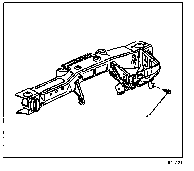
6. Install the bolt (1) to the cross vehicle beam.
Tighten
Tighten the bolt to 20 N.m (15 lb ft).
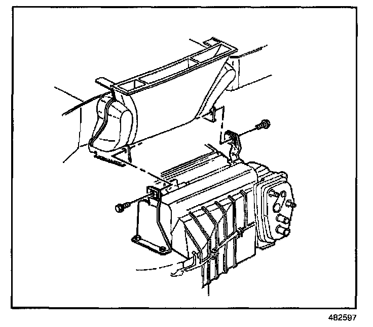
7. Install the upper support bracket bolts for the HVAC module.
Tighten
Tighten the bolts to 10 N.m (89 lb in).
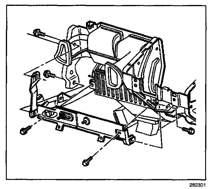
8. Install the HVAC module center support bracket.
9. Install the bolts to the center support bracket of the HVAC module.
Tighten
Tighten the bolts to 10 N.m (89 lb in).
10. Install the instrument panel wiring harness on to the cross vehicle beam and secure the retaining clips.
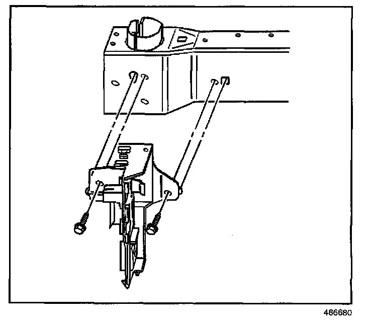
11. Install the BCM bracket and the retaining bolts.
Tighten
Tighten the bolts to 10 N.m (89 lb in).
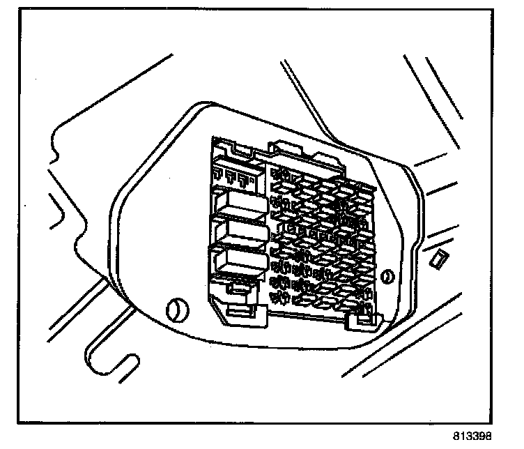
12. Install the fuse block to the holder.
13. Install the two screws below the fuse block that hold the main wire harness connector to the cross car beam.
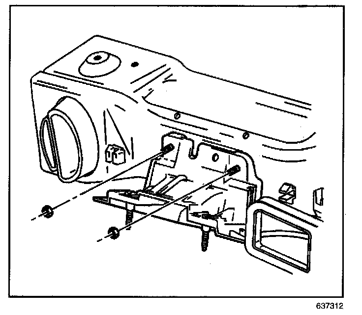
14. Install the support bracket and bolts for the steering column.
Tighten
Tighten the bolts to 50 N.m (37 lb ft).
15. Install the brake pedal.
16. Install the passenger side SIR inflator module.
17. Install the air distribution ducts.
18. Install the IP trim pad.
19. Connect the battery negative cable.