Control Valve Body Cover Replacement
Control Valve Body Cover Replacement
Removal Procedure
Important: Lock steering wheel in centered position with wheels straight ahead.
1. Remove the engine dress cover.
2. Remove the air cleaner intake duct. Refer to Air Cleaner Inlet Duct Replacement .
3. Remove the engine mount struts. Refer to Engine Mount Strut Replacement .
Important: For supercharged engines, remove the throttle cable bracket.
4. Disconnect the shift cable bracket.
5. Remove the transaxle top side cover bolt.
6. Install the engine support fixture. Refer to Engine Support Fixture .
7. Disconnect the transmission wiring harness connector.
8. Raise and support the vehicle.
9. Remove the left front tire and wheel assembly.
10. Remove the left inner splash shield 3 push pins.
11. Loosen the wheel speed sensor harness from the 5 retainers at the cradle.
12. Remove the transmission support to cradle nuts only. Refer to Transmission Mount Replacement .
13. Raise the vehicle.
14. Remove the front splash shield 5 bolts.
15. Loosen the engine mount lower nuts. Refer to Engine Mount Bracket Replacement .
16. Remove the stabilizer bolts and reposition the stabilizer.
17. Remove the steering gear cradle bolts, then support gear before lowering cradle.
18. Support the left side of the frame with a jackstand.
19. Remove the left side frame bolts. DO NOT loosen the right front or the right rear frame bolts. Refer to Frame Replacement .
20. Remove the left ball joint from the steering knuckle.
21. Position the drain pan under the transaxle.
22. Remove the left drive axle from the transaxle. Refer to Wheel Drive Shaft Replacement .
23. Secure the drive axle to the steering knuckle/strut.
24. Adjust the jackstand to lower the left side of the frame until it hangs free. Remove jack stand.
25. Lower vehicle to access engine support fixture.
26. Lower the engine/transmission assembly with the engine support fixture to gain access to remaining side cover bolts.
27. If replacing the side cover, remove 4 engine mount bracket bolts.
28. Remove the harness retainer.
29. Raise vehicle to access side cover bolts.
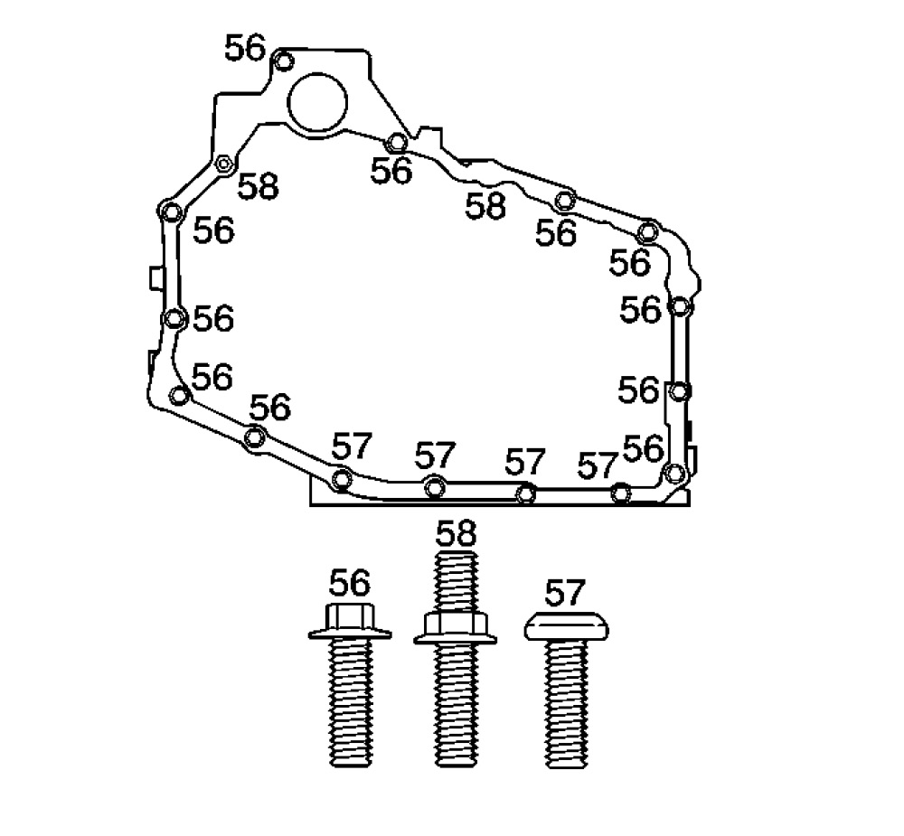
30. Remove the case side cover bolts (56-58).

31. Remove the case side cover pan (53).
32. Remove the case side cover gasket (54).
33. Clean the case.
34. Clean the side cover gasket mating surfaces.
Installation Procedure
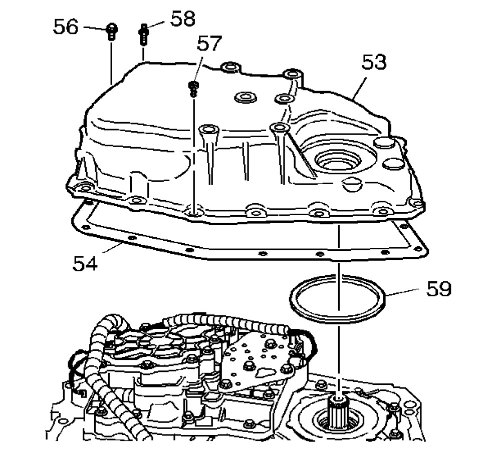
1. Install the case side cover gasket (54).
2. Install the case side cover pan (53).

Notice: Use the correct fastener in the correct location. Replacement fasteners must be the correct part number for that application. Fasteners requiring replacement or fasteners requiring the use of thread locking compound or sealant are identified in the service procedure. Do not use paints, lubricants, or corrosion inhibitors on fasteners or fastener joint surfaces unless specified. These coatings affect fastener torque and joint clamping force and may damage the fastener. Use the correct tightening sequence and specifications when installing fasteners in order to avoid damage to parts and systems.
3. Install the case side cover bolts (56-58) except for the top bolt.
Tighten
Tighten bolts (56-58) to 25 Nm (18 lb ft).
4. Install the left drive axle to the transaxle. Refer to Wheel Drive Shaft Replacement .
5. Raise the vehicle.
6. Use a jackstand to raise the left side of the cradle and engine assembly into position.
7. Install the left ball joint into knuckle.
8. Install the left side frame bolts .
Tighten
Tighten the bolts to 165 Nm (122 lb ft).
9. Install the engine mount lower nuts. Refer to Engine Mount Bracket Replacement .
10. Install the transaxle mount nuts.
Tighten
Tighten the nuts to 47 Nm (35 lb ft).
11. Remove the jackstands from the frame.
12. Remove the drain pan from under the transaxle.
13. Install the ball joint nut, and cotter pin.
14. Install the steering gear cradle bolts.
Tighten
Tighten the bolts to 80 Nm (59 lb ft).
15. Reposition the stabilizer and install the stabilizer bolts .
Tighten
Tighten the bolts to 23 Nm (17 lb ft).
16. Install the front splash shield 5 bolts.
17. Lower the vehicle.
18. Install two engine mount bolts.
Tighten
Tighten the bolts to 47 Nm (35 lb ft).
19. Install the wheel speed sensor harness to the 5 retainers at the cradle.
20. Install the left inner splash shield 3 push pins.
21. Install the left front tire and wheel assembly.
22. Lower the vehicle.
23. Remove the engine support fixture.
24. Connect the shift cable bracket.
25. Install the transaxle top side cover bolt.
26. Connect the transaxle wiring harness connector.
Important: Install the throttle cable bracket, if previously removed (Supercharged) .
27. Install the engine mount struts. Refer to Engine Mount Strut Replacement .
28. Install the throttle body air inlet duct. Refer to Air Cleaner Inlet Duct Replacement .
29. Install the engine dress cover.
Notice: Check the transmission fluid level immediately after adding fluid and before vehicle operation. Do not overfill the transmission. An overfilled transmission may result in foaming or fluid to be expelled out the vent tube when the vehicle is operated. Overfilling will result in possible damage to the transmission
30. Check and fill the transaxle as necessary.
31. Inspect for fluid leaks.