E6 Checking the Injectors
E6 Checking the injectorsTools:
- Multimeter
Before starting any checking work on the injectors, unplug the control module and mass air flow sensor connectors.
Note: Readings must be taken at the rear of the control module connector with its cover removed.
1 Unplug the control module and mass air flow sensor connectors. Remove the cover from the control module connector.
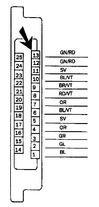
2 Measure the resistance across pin 13 (green/ red; GN/RD) of the control module and pin 87 of the pump relay. The resistance should be 4 ohms. If it is not, continue as described below.
3 Unplug the injector connector.
Measure the resistance of the injector by connecting the multimeter to its connecting pins.
The reading should be 16 ohms at 2000 (68°F) if the injector is OK.
If a correct reading is not obtained, fit a new injector.
4 If the correct reading is obtained, check the wiring between pin 13 (green/red; GN/RD) of the control module and the injectors (via the distribution points). Peel back the rubber dust excluders and, from the rear of the connector, check the blue/red lead between pin 87 of the fuel pump relay and the injectors via the distribution block.