Test Readings, Control Module Connections
Test Readings, Control Module Connections:
The following pages contain instructions and readings for testing the control module.
Remember:
^ Note the test condition, and use common sense when assessing the test result.
^ The specified test readings are with the ignition ON, unless otherwise stated.
^ Check these points:
^ First check that the control module is supplied with current and is grounded.
^ Then check all sensor inputs and signals from other systems.
^ Finally, check the control module outputs. Remember that the test readings do not indicate whether the actuator is working.
^ If any reading is not OK, consult the wiring diagram to trace the leads, connectors or components which should be checked more thoroughly.
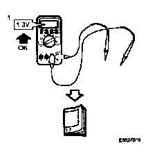
^ The test readings given apply to a calibrated Fluke 88/97.
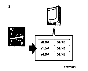
^ The test readings show the signal pulse condition or pulse length. A test instrument with pulse rate or width measurement must be used.
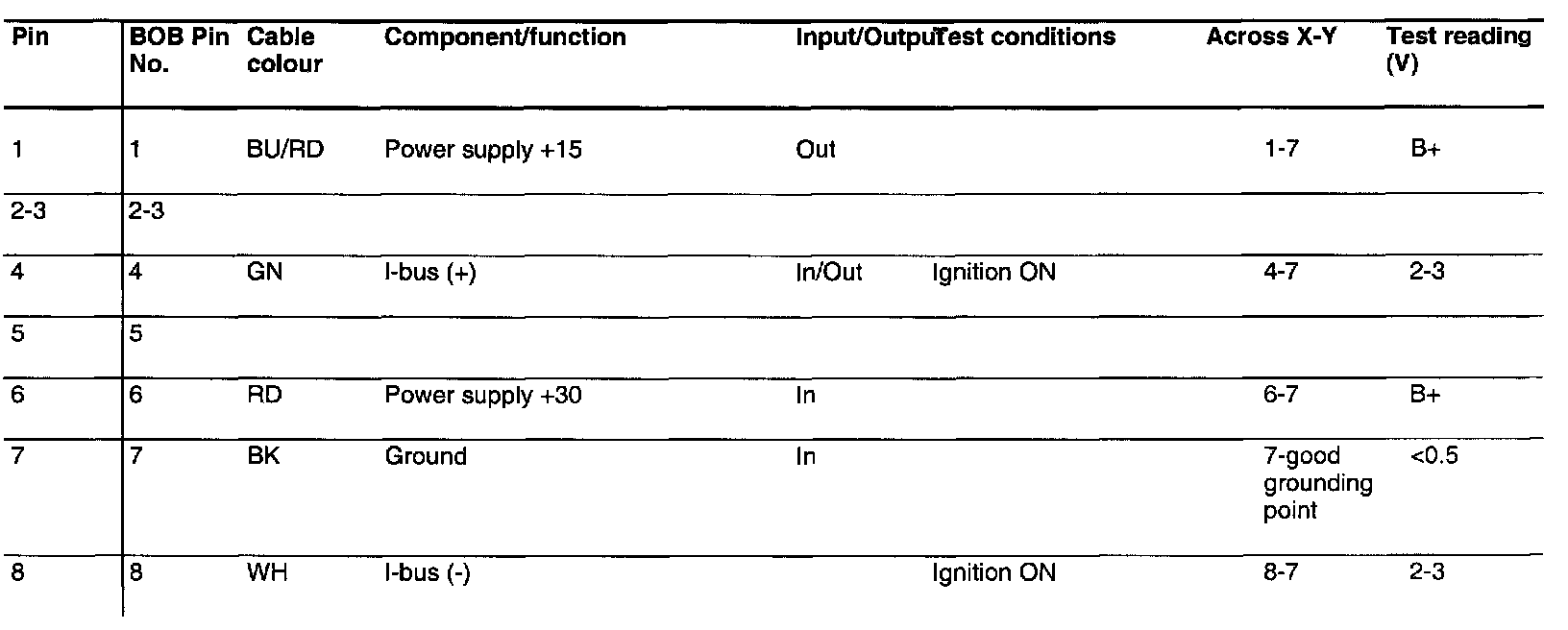
Connector 1 (K1), test readings
Pin No 1 - 8:
Connector 2 (K2), test readings
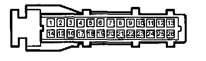
Pin No 1 - 26:

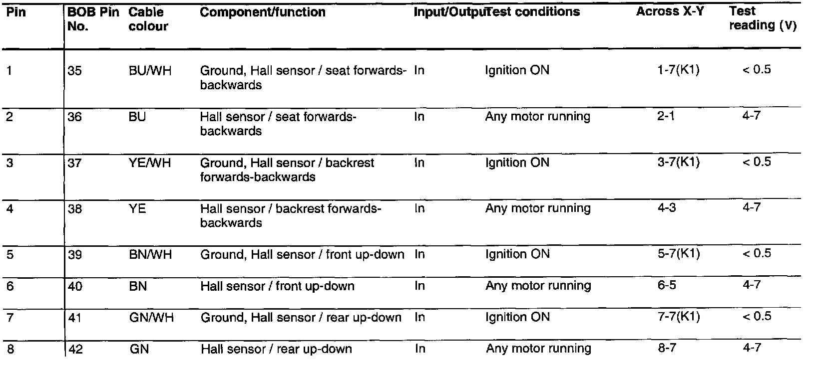
Connector 3 (K3), test readings
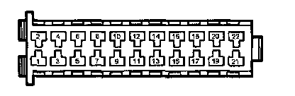
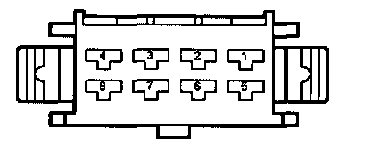
Pin No 1 - 8:
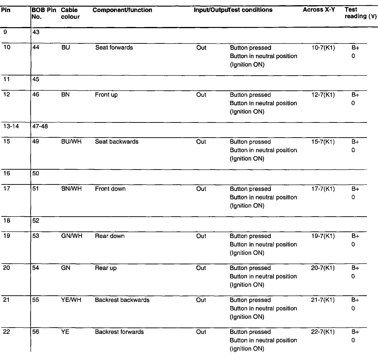
Pin No 9 - 22: