Test Readings, Control Module Connections
Scope
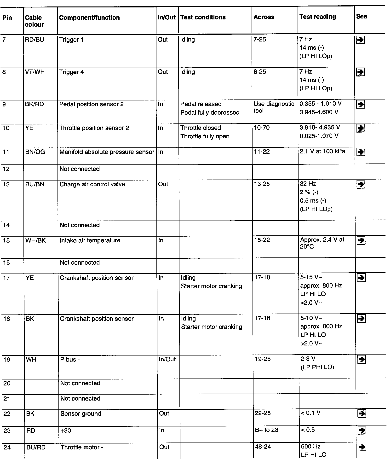
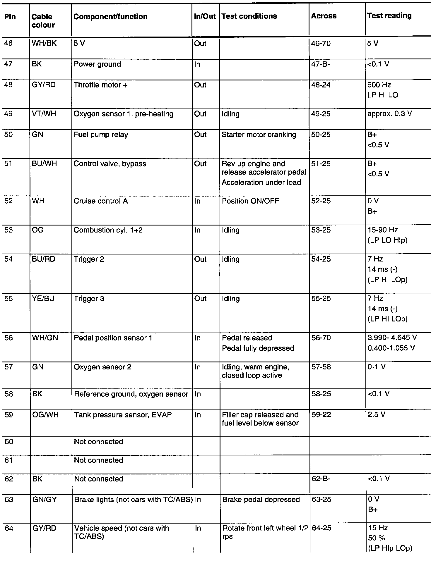
The following pages contain readings and directions for measuring signals and levels on the Trionic control module.
Remember
- Note the test readings, use common sense when assessing the results of the tests.
- The specified values are with the ignition in the ON position unless otherwise stated.
- First, make sure the control module is supplied with power and grounded.
- Then, check all the sensor inputs and signals from other systems.
- Finally, check the control module outputs. Remember that the test readings do not indicate whether the actuator is working.
- If any of the test readings is incorrect, use the wiring diagram to determine which lead, connector or component should be checked further.
- The specified test values apply for a Fluke 88/97.
- The test readings % (+) and ms (+) signify the pulse ratio and pulse length of the signal respectively. A test instrument capable of measuring pulse ratio and pulse width must be used. The sign indicates a positive trigger pulse, TRIG+.

> = greater than
< = less than
~ = alternating current
Pins without further comments have no connection. (LP: LOGIC PROBE P = select pulse; p = visible pulses).
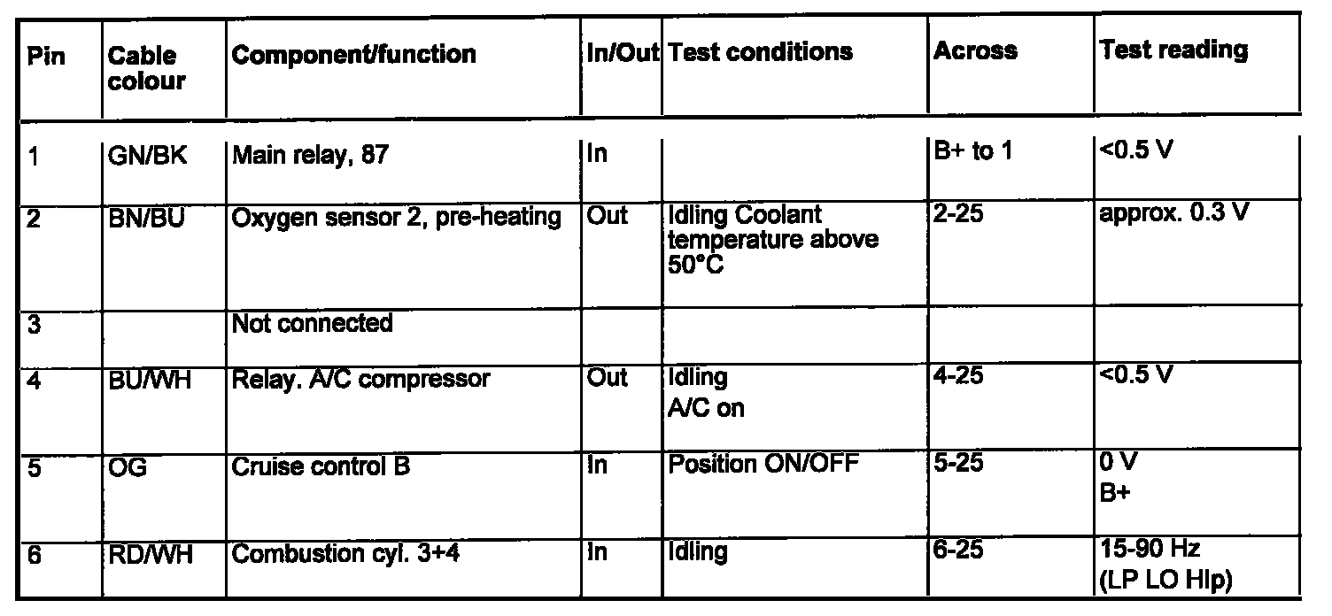
Pin No. 1 - 6:
Pin No. 7 - 24:
Pin No 25 - 45:
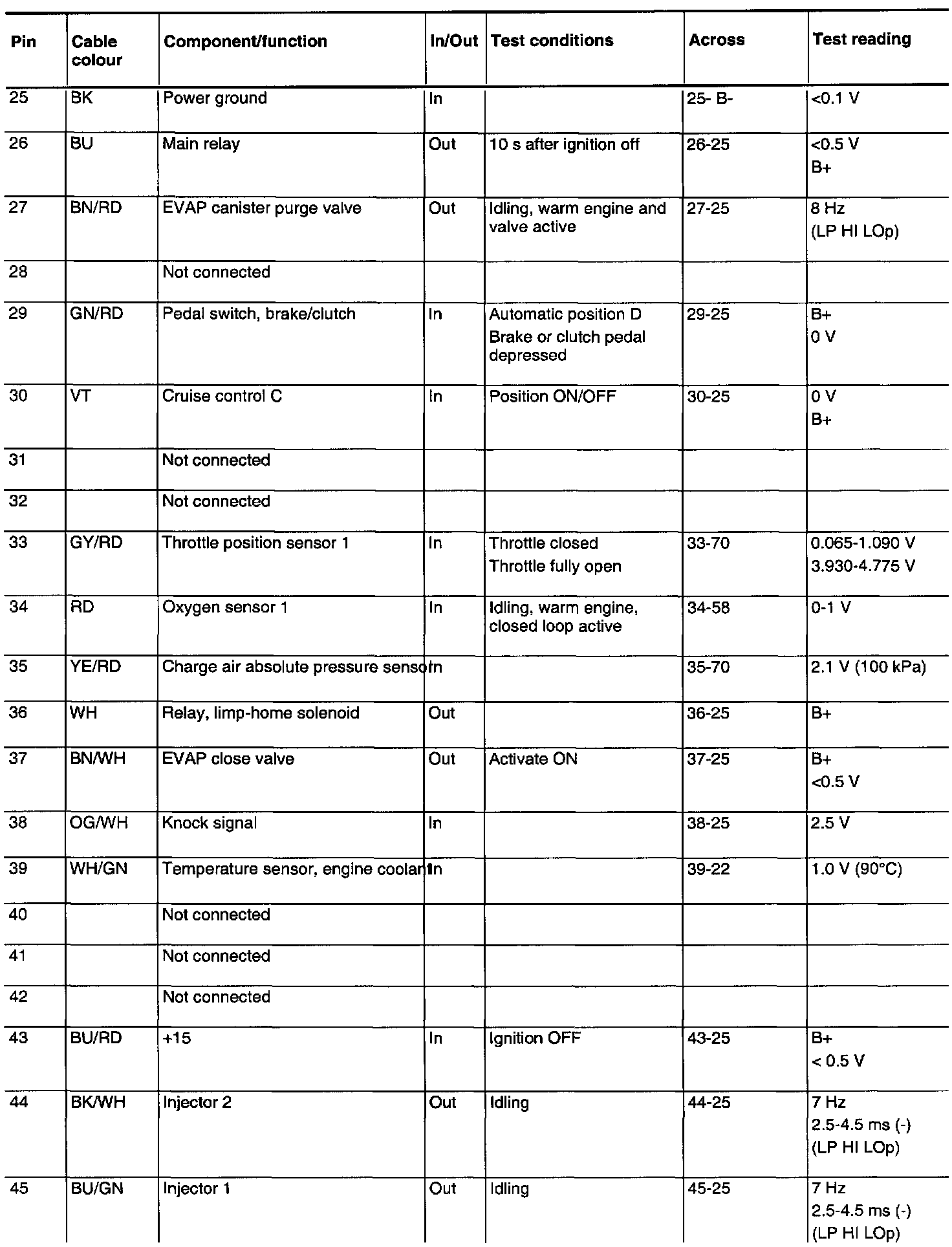
Pin No. 46 - 64:
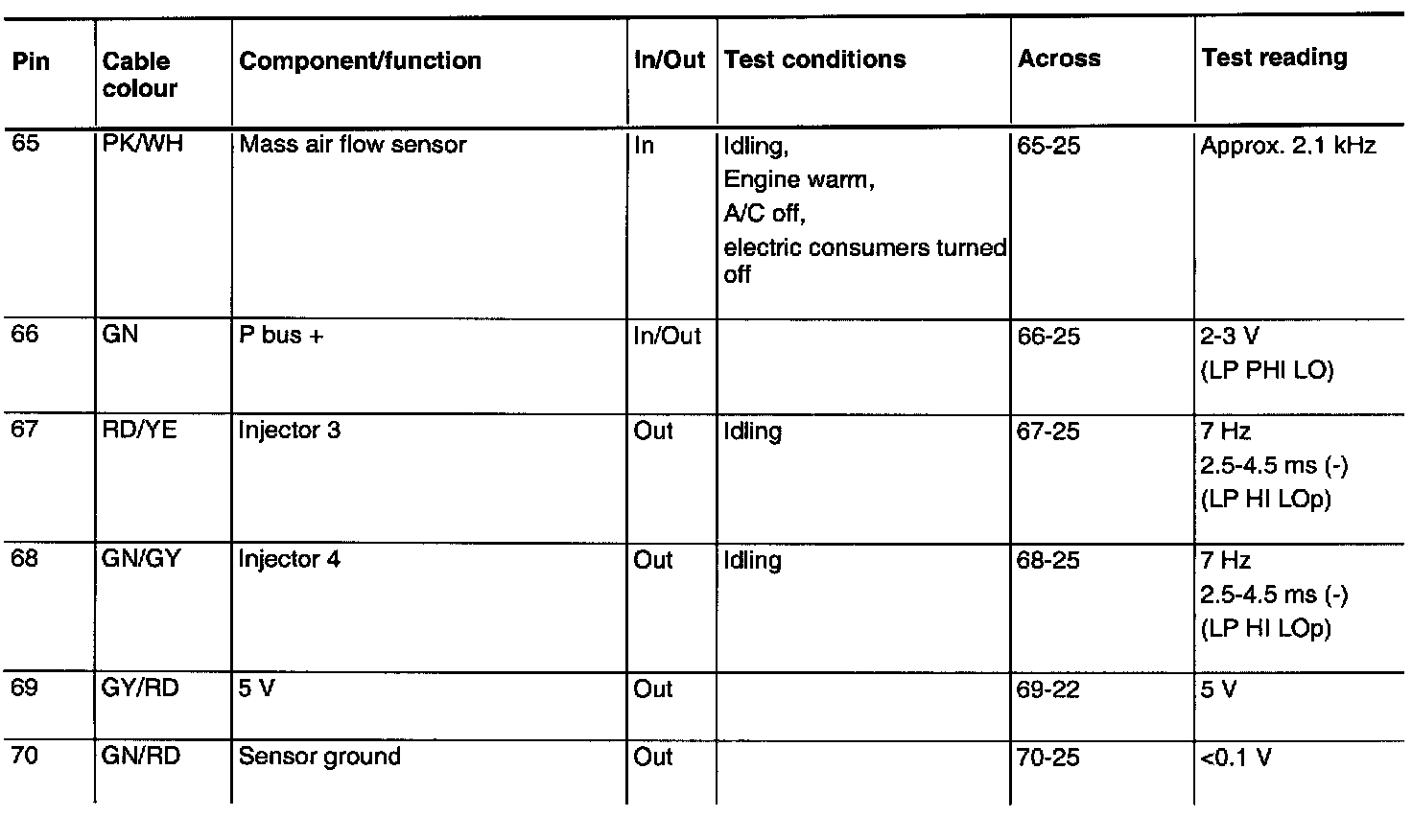
Pin No. 65 - 70: