All Doors Lock/Unlock Functions Do Not Operate Via Master Switch, Driver Side Door Key Cylinder
DOOR LOCK: POWER DOOR LOCK CONTROL SYSTEM: All Doors LOCK/UNLOCK Functions do not Operate Via Master Switch, Driver Side Door Key Cylinder
- All Doors LOCK/UNLOCK Functions do not Operate Via Master Switch, Driver Side Door Key Cylinder
DESCRIPTION
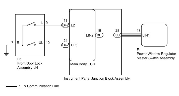
The main body ECU receives switch signals from the power window regulator master switch assembly, and driver side door key cylinder switch signals from the front door lock assembly LH. The main body ECU activates the door lock motor on each door according to these signals.
WIRING DIAGRAM
INSPECTION PROCEDURE
PROCEDURE
1. CHECK DOOR LOCK OPERATION
(a) Check door lock operation Operation Check.
Result
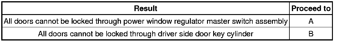
B -- READ VALUE USING TECHSTREAM (DOOR KEY LINKED LOCK AND UNLOCK SWITCH)
A -- Continue to next step.
2. CHECK DTC OUTPUT (LIN COMMUNICATION SYSTEM)
(a) Clear the DTC Reading and Clearing Diagnostic Trouble Codes.
(b) Check for DTCs Reading and Clearing Diagnostic Trouble Codes.
OK:
DTC B1206 is not output.
NG -- GO TO LIN COMMUNICATION SYSTEM (DTC B1206) B1206
OK -- Continue to next step.
3. REPLACE POWER WINDOW REGULATOR MASTER SWITCH ASSEMBLY
(a) Replace the power window regulator master switch assembly Removal.
NEXT -- Continue to next step.
4. CHECK DOOR LOCK OPERATION
(a) Check that all doors can be locked and unlocked by using the power window regulator master switch assembly Operation Check.
OK:
All doors can be locked and unlocked with the power window regulator master switch assembly.
NG -- REPLACE MAIN BODY ECU Removal
OK -- END (POWER WINDOW REGULATOR MASTER SWITCH ASSEMBLY WAS DEFECTIVE)
5. READ VALUE USING TECHSTREAM (DOOR KEY LINKED LOCK AND UNLOCK SWITCH)
(a) Connect the Techstream to the DLC3.
(b) Turn the ignition switch to ON.
(c) Turn the Techstream on.
(d) Enter the following menus: Body Electrical / Main Body / Data List.
(e) According to the display on the Techstream, read the Data List.
Main Body
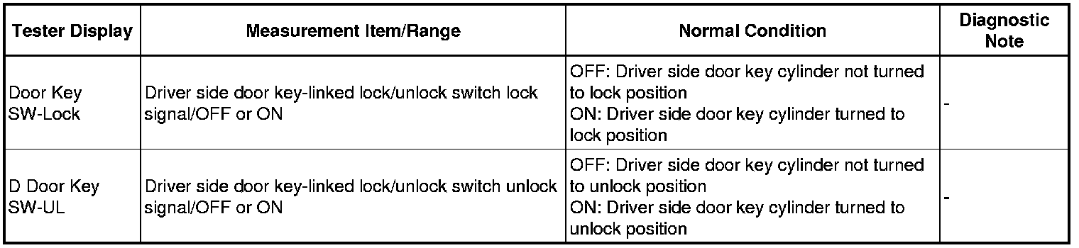
OK:
The Techstream indicates ON or OFF according to the key cylinder operation shown in the table.
NG -- INSPECT FRONT DOOR LOCK ASSEMBLY LH (DOOR KEY LINKED LOCK AND UNLOCK SWITCH)
OK -- REPLACE MAIN BODY ECU Removal
6. INSPECT FRONT DOOR LOCK ASSEMBLY LH (DOOR KEY LINKED LOCK AND UNLOCK SWITCH)
(a) Remove the front door lock assembly LH Removal.
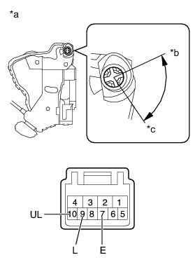
(b) Measure the resistance according to the value(s) in the table below.
Standard Resistance:
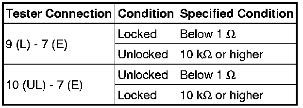
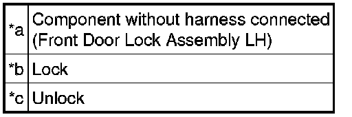
Text in Illustration
(c) Reinstall the front door lock assembly LH.
NG -- REPLACE FRONT DOOR LOCK ASSEMBLY LH Removal
OK -- Continue to next step.
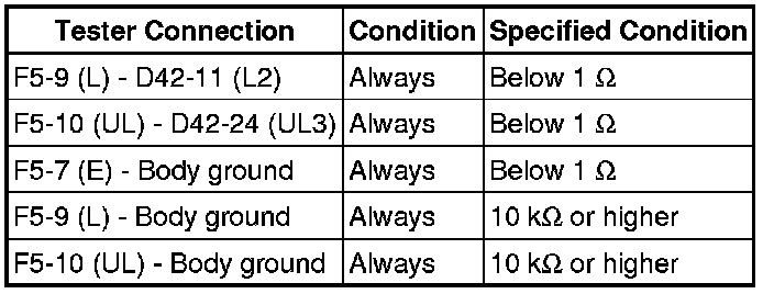
7. CHECK HARNESS AND CONNECTOR (FRONT DOOR LOCK ASSEMBLY LH - MAIN BODY ECU AND BODY GROUND)
(a) Disconnect the F5 front door lock assembly LH connector.
(b) Disconnect the D42 main body ECU connector.
(c) Measure the resistance according to the value(s) in the table below.
Standard Resistance:
(d) Reconnect the main body ECU connector.
(e) Reconnect the front door lock assembly LH connector.
NG -- REPAIR OR REPLACE HARNESS OR CONNECTOR
OK -- REPLACE MAIN BODY ECU Removal